Introduction to Water Level Indicators
A water level indicator is a practical and cost-effective electronic project that helps monitor the water level in tanks, preventing overflow or dry running of pumps. This beginner-friendly DIY project uses basic components like transistors, LEDs, and a buzzer to visually and audibly indicate water levels. In this article, we’ll break down a simple water level indicator circuit, explain how it works, and guide you through building your own.
Understanding the Water Level Indicator Circuit
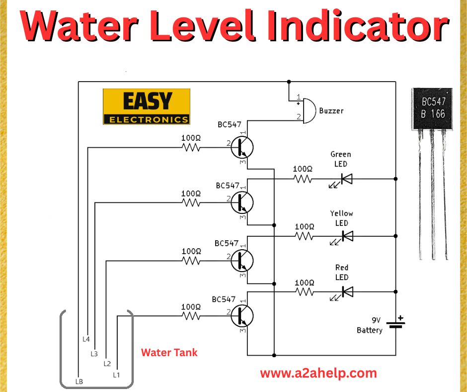
The circuit diagram shown uses four BC547 transistors, LEDs (green, yellow, red), a buzzer, resistors, and a 9V battery to monitor water levels in a tank. The setup includes four sensing probes (L1 to L4) placed at different heights in the tank, with a common probe (LB) at the base. Here’s a quick overview of the components:
- BC547 Transistors: Act as switches to control the LEDs and buzzer.
- LEDs: Indicate water levels—green for low, yellow for medium, and red for high.
- Buzzer (B 166): Sounds an alarm when the tank is full.
- Resistors (100Ω and 1000Ω): Limit current to protect the LEDs and transistors.
- 9V Battery: Powers the circuit.
How the Water Level Indicator Works
The circuit operates on a simple principle: water conducts electricity, completing the circuit between the probes and the common probe (LB). Here’s the step-by-step working:
- Base Probe (LB): This probe is always in contact with the water at the tank’s base and is connected to the positive terminal of the battery.
- Level Probes (L1 to L4): These probes are placed at increasing heights in the tank, each connected to the base of a BC547 transistor.
- Water Level Detection:
- When water reaches a probe (e.g., L1), it completes the circuit between LB and L1, allowing current to flow to the base of the first BC547 transistor.
- The transistor turns on, lighting up the corresponding LED (green for L1, yellow for L2, red for L3).
- As the water level rises to L4, the fourth transistor activates the buzzer, indicating the tank is full.
- Visual and Audible Alerts: The LEDs provide a visual indication of the water level, while the buzzer alerts you when the tank is full, helping prevent overflow.
Components Needed for the Water Level Indicator
To build this water level indicator, gather the following components:
- BC547 transistors (4 pieces)
- LEDs: 1 green, 1 yellow, 1 red
- Buzzer (B 166)
- Resistors: 100Ω (4 pieces), 1000Ω (4 pieces)
- 9V battery and connector
- Wires for probes (use stainless steel or copper wires to avoid corrosion)
- Breadboard or PCB for assembly
- Water tank for testing

Step-by-Step Guide to Build the Water Level Indicator
- Prepare the Probes:
- Use four stainless steel wires as probes (L1 to L4) and one as the base probe (LB).
- Position them at different heights in the tank, ensuring LB is at the bottom.
- Assemble the Circuit:
- Connect the collector of each BC547 transistor to the positive terminal of an LED (via a 100Ω resistor).
- Connect the negative terminal of each LED to the ground (negative terminal of the battery).
- Connect the emitter of each transistor to the ground.
- Attach a 1000Ω resistor between the base of each transistor and the corresponding probe (L1 to L4).
- For the fourth transistor, connect the buzzer in parallel with the red LED.
- Power the Circuit:
- Connect the 9V battery to the circuit, ensuring the base probe (LB) is connected to the positive terminal.
- Test the Circuit:
- Place the probes in the tank and add water gradually.
- Observe the LEDs lighting up as the water level rises and the buzzer sounding when the water reaches the highest probe (L4).
Advantages of This Water Level Indicator
- Cost-Effective: Uses affordable components, making it ideal for DIY enthusiasts.
- Easy to Build: Simple design suitable for beginners in electronics.
- Customizable: Add more probes and LEDs to monitor additional levels.
- Energy Efficient: Consumes minimal power, running on a 9V battery.
Applications of Water Level Indicators
Water level indicators are widely used in:
- Domestic water tanks to prevent overflow.
- Industrial settings to monitor liquid levels in storage tanks.
- Agricultural systems to manage water levels for irrigation.
- Aquariums to maintain optimal water levels for aquatic life.
Troubleshooting Tips
- LEDs Not Lighting Up: Check the connections and ensure the probes are in contact with water. Verify the battery voltage.
- Buzzer Not Working: Ensure the buzzer is functional and properly connected. Test the fourth transistor for faults.
- False Readings: Clean the probes to remove any corrosion or debris that might interfere with conductivity.
Conclusion
This simple water level indicator circuit is a fantastic project for electronics beginners. With just a few components, you can build a reliable system to monitor water levels in a tank, saving time and preventing wastage. Whether you’re a hobbyist or looking for a practical solution for your home, this DIY project is both educational and functional.
