Introduction to Passive Tone Control
If you’re an audio enthusiast or an electronics hobbyist, you’ve likely come across the term “passive tone control circuit.” This simple yet effective circuit allows you to adjust the bass and treble frequencies of an audio signal without the need for an external power supply. In this article, we’ll dive deep into the workings of a passive tone control circuit, analyze the provided schematic diagram, and explore its components and applications. Whether you’re building your own audio equipment or troubleshooting an existing setup, this guide will equip you with the knowledge you need.
What is a Passive Tone Control Circuit?
A passive tone control circuit is a type of audio filter that modifies the frequency response of an audio signal using passive components like resistors, capacitors, and potentiometers. Unlike active tone controls, which rely on operational amplifiers and a power source, passive circuits are cost-effective and straightforward, making them a popular choice for DIY audio projects.

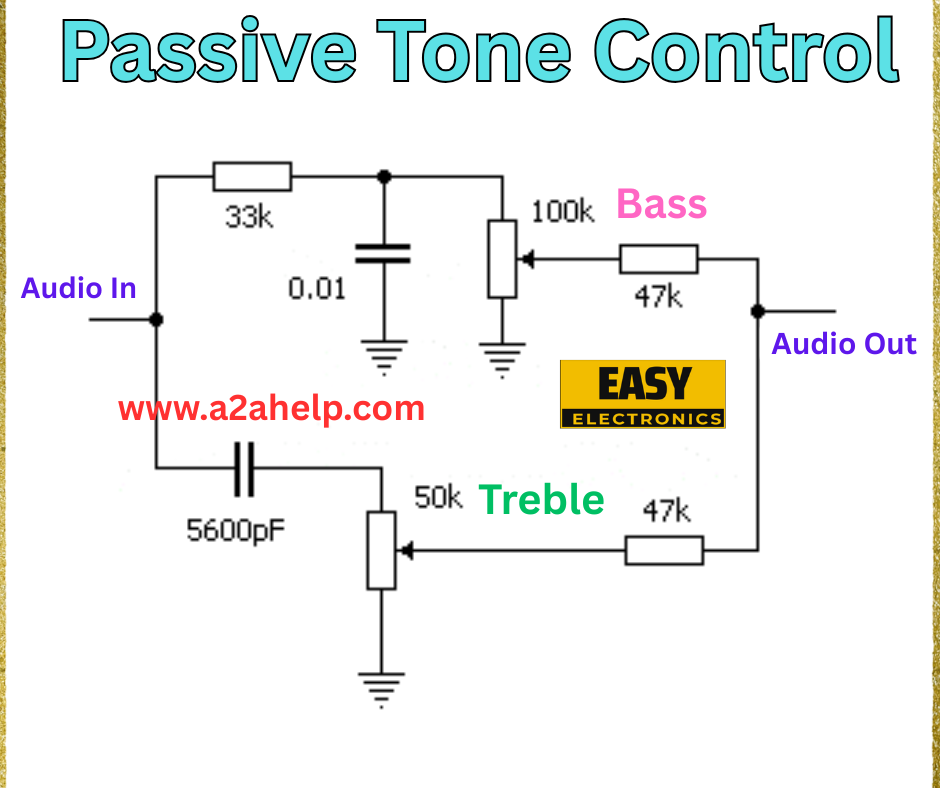
Analyzing the Passive Tone Control Schematic
Key Components
- 33k Resistor: Connected to the audio input, this resistor helps set the input impedance and ensures proper signal flow.
- 0.01 µF Capacitor: Paired with the 33k resistor, this capacitor forms a high-pass filter, allowing higher frequencies to pass while attenuating lower ones.
- 100k Potentiometer (Bass Control): This variable resistor adjusts the bass levels. Turning it changes the resistance, altering the low-frequency response.
- 47k Resistor: Works in conjunction with the 100k potentiometer to fine-tune the bass output.
- 5600 pF Capacitor: Acts as part of the treble control network, affecting high-frequency signals.
- 50k Potentiometer (Treble Control): This adjustable resistor controls the treble levels, allowing you to boost or cut high frequencies.
- 47k Resistor: Assists in shaping the treble response when used with the 50k potentiometer.
- Audio In and Audio Out: The input and output points where the audio signal enters and exits the circuit.
Circuit Functionality
The circuit splits the audio signal into two paths: one for bass and one for treble. The 0.01 µF capacitor and 33k resistor filter out low frequencies at the input stage. The 100k potentiometer then adjusts the bass, while the 5600 pF capacitor and 50k potentiometer handle the treble. The 47k resistors stabilize the output, ensuring a balanced audio signal.
How Passive Tone Control Works
Passive tone control circuits operate by altering the impedance of the signal path. The potentiometers (variable resistors) allow you to manually adjust the cutoff frequencies for bass and treble. For instance:
- Increasing the resistance on the bass potentiometer boosts low frequencies.
- Adjusting the treble potentiometer increases or decreases high-frequency output.
Since this is a passive design, the overall signal amplitude may decrease slightly due to the lack of amplification. However, this trade-off is minimal for many applications, especially in guitar pedals, hi-fi systems, and small audio amplifiers.
Advantages of Passive Tone Control
- No Power Supply Needed: Ideal for battery-operated or low-power devices.
- Cost-Effective: Uses inexpensive components, making it accessible for hobbyists.
- Simplicity: Easy to design and implement with basic electronics knowledge.
Limitations
- Signal Loss: Passive circuits can attenuate the signal, requiring a preamplifier in some cases.
- Limited Range: The adjustment range is narrower compared to active tone controls.
Applications of Passive Tone Control
Passive tone control circuits are widely used in:
- Guitar Effects Pedals: To shape the sound of electric guitars.
- Hi-Fi Audio Systems: For basic tone adjustment in vintage equipment.
- DIY Audio Projects: Perfect for enthusiasts experimenting with audio electronics.
Building Your Own Passive Tone Control Circuit
To replicate the circuit from the image:
- Gather the components: 33k and 47k resistors, 0.01 µF and 5600 pF capacitors, 100k and 50k potentiometers.
- Connect the audio input to the 33k resistor and 0.01 µF capacitor network.
- Wire the 100k potentiometer for bass control and the 50k potentiometer for treble, as shown.
- Link the 47k resistors to the output stage and test with an audio source.
Always double-check your connections and use a multimeter to ensure accuracy. For detailed guidance, visit resources like www.a2ahelp.com.
Conclusion
Passive tone control circuits are a fantastic way to enhance your audio projects without complicating your setup. The schematic from Easy Electronics provides a solid foundation for understanding and building your own. Whether you’re tweaking a guitar tone or refining a home audio system, this circuit offers a practical solution. For more electronics tutorials and schematics, keep exploring our site, and feel free to share your projects with us!
