Introduction
The TIP3055/TIP2955 amplifier circuit is a go-to solution for DIY audio enthusiasts aiming to create a high-power audio amplifier. Using the robust TIP3055 (NPN) and TIP2955 (PNP) transistors, this circuit delivers exceptional sound quality for a 4Ω speaker. In this SEO-optimized guide, we’ll explore the circuit diagram, explain its working principle, and provide a detailed step-by-step tutorial to help you build your own TIP3055/TIP2955 audio amplifier. Perfect for DIY audio projects, this amplifier ensures crystal-clear audio output for your speakers.
What is a TIP3055/TIP2955 Amplifier Circuit?
A TIP3055/TIP2955 amplifier is a push-pull audio amplifier that uses complementary transistors—TIP3055 (NPN) and TIP2955 (PNP)—to amplify audio signals efficiently. Powered by a dual power supply of ±35V, this circuit drives a 4Ω speaker with low distortion and high power output. It’s an excellent choice for DIY audio amplifiers, home theater systems, or custom speaker setups requiring a reliable high-power amplifier circuit.
Components Needed for the TIP3055/TIP2955 Amplifier Circuit
To build this high-power audio amplifier, you’ll need:
- Power Transistors:
- TIP3055 (NPN): For the positive audio signal.
- TIP2955 (PNP): For the negative audio signal.
- Transistors:
- BC546 (NPN) x 2: For driver and bias stages.
- BC557 (PNP) x 2: Complements the BC546.
- Resistors:
- 47kΩ, 22kΩ, 4.7kΩ (x2), 2.2kΩ, 0.33Ω (x2), 10Ω, 100Ω.
- Capacitors:
- 1µF (input), 10µF (feedback), 150pF (compensation), 100nF (x2, decoupling), 220µF (x2, smoothing).
- Diodes:
- 1N4148 x 2: For bias stabilization.
- Speaker: 4Ω (RL).
- Power Supply: ±35V dual power supply (learn how to build one in our 12V Dual Power Supply Guide scaled to 35V).
- Wires and Breadboard/PCB: For assembling the DIY audio amplifier.

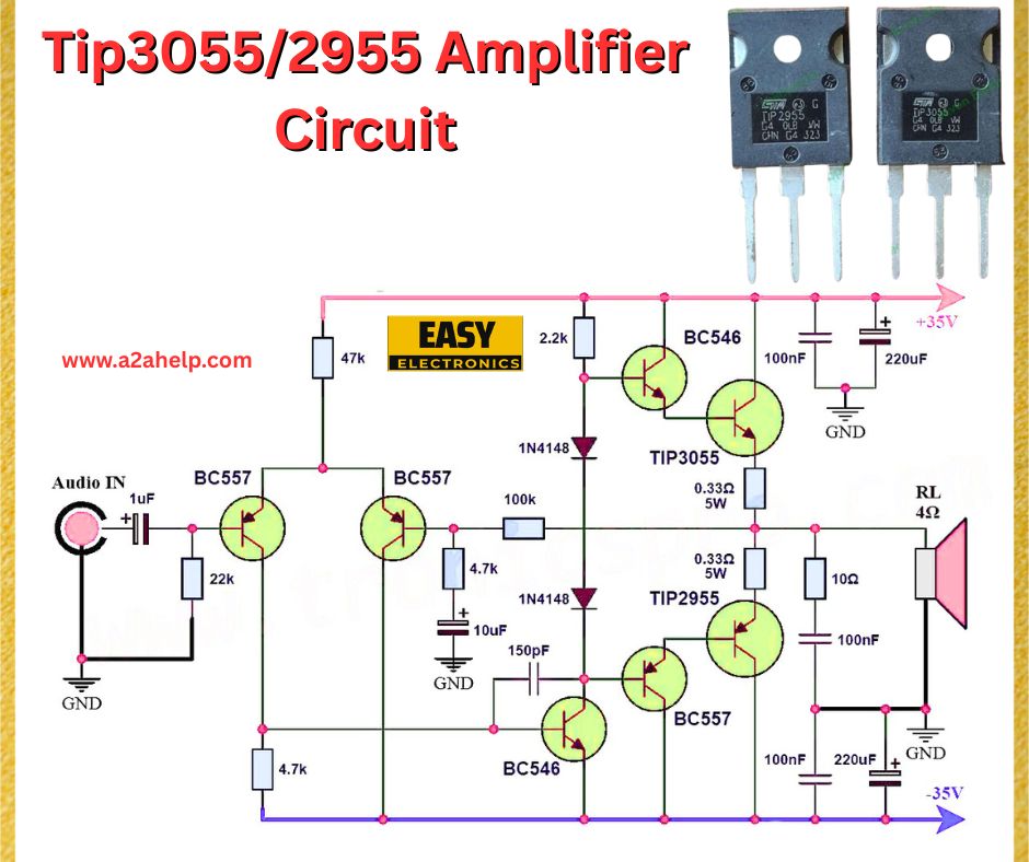
Circuit Diagram and Working Principle of the TIP3055/TIP2955 Amplifier
The TIP3055/TIP2955 amplifier circuit operates as a Class AB push-pull amplifier, minimizing crossover distortion while delivering high power. Here’s the working principle:
- Input Stage: A 1µF capacitor blocks DC while passing the AC audio signal. A 22kΩ resistor sets the input impedance.
- Differential Amplifier: Two BC557 transistors form a differential pair to amplify the signal. A 47kΩ resistor biases this stage, with a 4.7kΩ resistor and 10µF capacitor providing feedback for stability.
- Driver Stage: BC546 transistors, a 2.2kΩ resistor, and 1N4148 diodes drive the output transistors, ensuring proper biasing to reduce distortion.
- Output Stage: The TIP3055 and TIP2955 transistors work in a push-pull setup. The TIP3055 handles the positive signal, and the TIP2955 manages the negative signal, driving the 4Ω speaker. Two 0.33Ω resistors stabilize the output.
- Power Supply Filtering: 220µF and 100nF capacitors on the ±35V lines filter noise for a stable dual power supply.
This design ensures a clean, amplified audio signal for high-fidelity audio applications.
Step-by-Step Guide to Build a TIP3055/TIP2955 Audio Amplifier
Follow these steps to create your DIY TIP3055/TIP2955 amplifier:
- Set Up the Power Supply: Use a ±35V dual power supply. Check our guide on building a dual power supply and scale it to 35V. Connect the +35V, -35V, and ground.
- Assemble the Input Stage: Connect the 1µF capacitor to the audio input, followed by a 22kΩ resistor to ground. Link to the base of the first BC557 transistor.
- Build the Differential Amplifier: Use two BC557 transistors with a 47kΩ resistor to the +35V rail. Add a 4.7kΩ resistor, 10µF capacitor for feedback, and a 150pF capacitor for frequency compensation.
- Add the Driver Stage: Connect BC546 transistors with a 2.2kΩ resistor and two 1N4148 diodes for biasing. Link this to the bases of the TIP3055 and TIP2955.
- Connect the Output Stage: Set up the TIP3055 and TIP2955 in a push-pull configuration. Add 0.33Ω resistors to their emitters, and connect the output to the 4Ω speaker via a 100Ω resistor and 100nF capacitor.
- Add Power Supply Filtering: Place 220µF and 100nF capacitors across the ±35V lines to ground.
- Test the Amplifier: Input an audio signal (e.g., from a phone) and verify the output on the speaker. Use a multimeter to check voltages.
Applications of the TIP3055/TIP2955 Amplifier Circuit
- Home Audio Systems: Perfect for DIY home theater setups.
- Portable Audio Amplifiers: Great for high-power audio projects.
- Music Systems: Amplify audio in car stereos or party speakers.
- Educational Projects: Learn about push-pull amplifiers and audio circuit design.
Safety Tips for Building the TIP3055/TIP2955 Amplifier
- Mount TIP3055 and TIP2955 transistors on heatsinks to manage heat.
- Verify capacitor polarity and transistor orientation to avoid damage.
- Disconnect power during assembly to prevent short circuits.
Why Use TIP3055 and TIP2955 Transistors for Audio Amplifiers?
The TIP3055 and TIP2955 transistors are ideal for high-power audio amplifiers due to their high current capacity (15A) and voltage handling (±60V). Their complementary nature ensures efficient push-pull operation, delivering low distortion and high output power for DIY audio amplifiers.
Troubleshooting Common Issues in the TIP3055/TIP2955 Amplifier
- No Sound Output: Check the audio input, transistor connections, and power supply.
- Distorted Sound: Verify the 1N4148 diodes and feedback loop (10µF capacitor, 4.7kΩ resistor).
- Overheating Transistors: Ensure TIP3055 and TIP2955 are on heatsinks and check for output stage short circuits.
Conclusion
The TIP3055/TIP2955 amplifier circuit is an excellent project for building a high-power audio amplifier with superior sound quality. This push-pull amplifier design offers low distortion and high efficiency, making it ideal for DIY audio projects, home theater systems, and educational purposes. Follow this step-by-step guide to create your own TIP3055/TIP2955 audio amplifier and enjoy powerful, clear audio. Start building today and enhance your audio experience!
