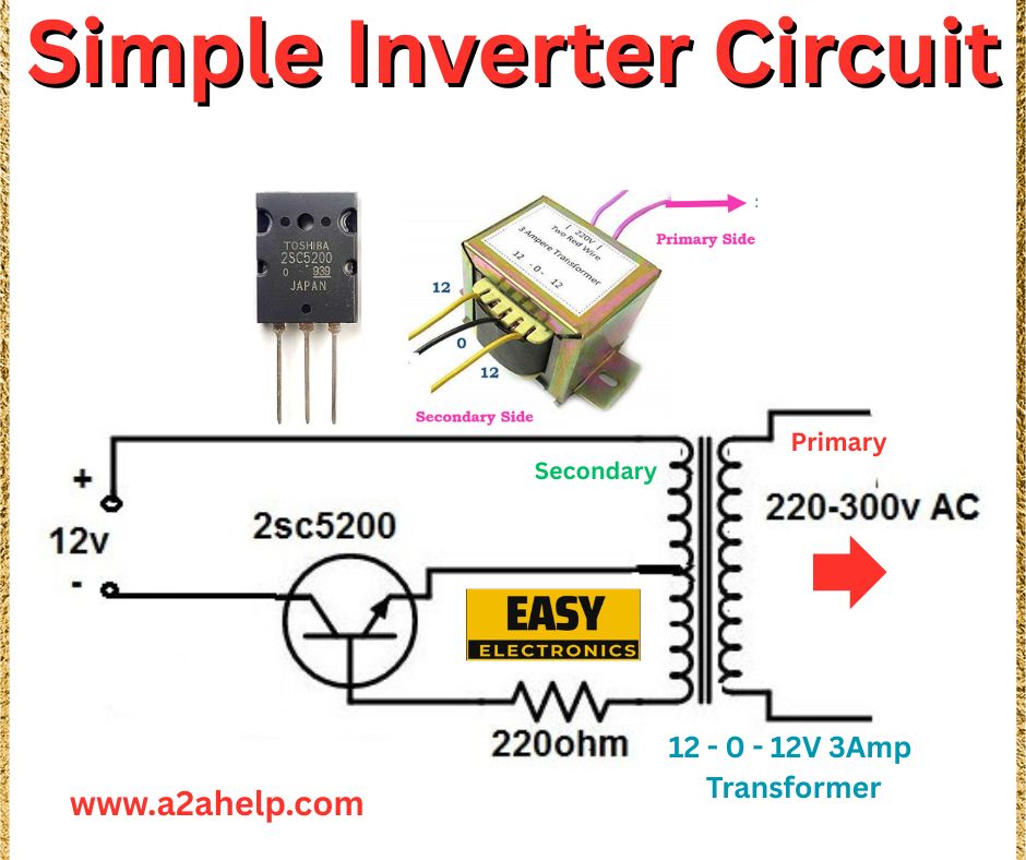
An inverter circuit is a fantastic project for anyone looking to convert DC power into AC power, enabling you to run household appliances from a battery. In this guide, we’ll explore a simple inverter circuit that transforms a 12V DC input into a 220-300V AC output using minimal components. Perfect for beginners and electronics enthusiasts, this tutorial will break down the circuit, explain its operation, and guide you through the building process. Let’s get started!
What Is an Inverter Circuit?
An inverter circuit converts direct current (DC) to alternating current (AC), making it possible to power AC devices from a DC source like a battery. This particular design uses a 12V DC input (such as from a car battery) to produce a 220-300V AC output, which can power small household appliances. The circuit relies on a power transistor and a transformer to achieve this conversion, making it a great introduction to inverter technology.
Components of the Simple Inverter Circuit
The circuit diagram includes the following components:
- Input Voltage: 12V DC (typically from a battery).
- Transistor (2SC5200): A high-power NPN transistor for switching.
- Resistor (200Ω): A 200Ω resistor to limit the base current of the transistor.
- Transformer (12-0-12V, 3A): A center-tapped transformer with a 12-0-12V secondary and 220-300V primary winding.
- Output: 220-300V AC from the transformer’s primary side.
How Does This Simple Inverter Circuit Work?
Let’s break down the operation of this circuit step by step:
- Oscillation with the Transformer and Transistor: The 2SC5200 transistor, combined with the 12-0-12V center-tapped transformer, forms a self-oscillating circuit. When the transistor switches on, current flows through one half of the secondary winding (from 12V to the center tap), inducing a voltage in the primary winding. When the transistor switches off, the magnetic field in the transformer collapses, and the other half of the secondary winding takes over, creating an alternating voltage.
- Base Drive with the Resistor: The 200Ω resistor connects the base of the 2SC5200 transistor to the opposite side of the transformer’s secondary winding. This provides positive feedback, ensuring the transistor oscillates at a frequency determined by the transformer’s characteristics (typically 50-60 Hz for a mains-compatible output).
- Voltage Step-Up with the Transformer: The transformer steps up the low-voltage AC (around 12V) from the secondary side to a high-voltage AC (220-300V) on the primary side. The 12-0-12V, 3A transformer is designed to handle the current and voltage requirements, producing a usable AC output.
- Output AC Voltage: The output from the transformer’s primary side is 220-300V AC, suitable for powering small appliances. Note that the exact output voltage depends on the transformer’s turns ratio and the load connected.

Why Build This Simple Inverter Circuit?
This inverter circuit is ideal for several reasons:
- Minimal Components: It uses just a transistor, a resistor, and a transformer, making it easy to assemble.
- Cost-Effective: The components are affordable and widely available.
- Educational Value: It teaches the basics of inverters, transformers, and transistor switching.
- Practical Use: It can power small AC devices in off-grid situations, like during camping or power outages.
However, this circuit is very basic and lacks features like overcurrent protection, voltage regulation, or a pure sine wave output (it produces a square or modified square wave). For sensitive electronics, you may need a more advanced inverter design.
How to Build This Simple Inverter Circuit
Here’s a step-by-step guide to assembling the circuit:
- Gather Your Components: Source a 2SC5200 transistor, a 200Ω resistor, and a 12-0-12V, 3A transformer with a 220-300V primary winding.
- Connect the Transformer: Identify the transformer’s secondary (12-0-12V) and primary (220-300V) sides. The secondary has three terminals: two 12V ends and a center tap.
- Wire the Transistor: Connect the collector of the 2SC5200 to one of the 12V ends of the transformer’s secondary. Connect the emitter to the negative terminal of the 12V DC supply.
- Add the Resistor: Solder the 200Ω resistor between the base of the 2SC5200 and the other 12V end of the transformer’s secondary.
- Connect the Power Supply: Attach the center tap of the transformer’s secondary to the positive terminal of the 12V DC supply. Connect the negative terminal of the supply to the emitter of the transistor.
- Output Connection: The transformer’s primary side (220-300V) is your AC output. Connect your load (e.g., a small appliance) to these terminals.
- Test the Circuit: Apply 12V DC (e.g., from a car battery) and measure the output voltage. Ensure the load doesn’t exceed the transformer’s 3A rating.
Safety Considerations
- High Voltage Warning: The output is 220-300V AC, which can cause a severe shock. Insulate all connections and handle with care.
- Current Rating: The transformer is rated for 3A. Overloading it can cause overheating or failure.
- Heat Dissipation: The 2SC5200 transistor may get hot during operation. Use a heatsink to prevent damage.
- Square Wave Output: The output is not a pure sine wave, which may not be suitable for sensitive electronics like laptops or medical devices.
Applications of This Simple Inverter Circuit
This circuit can be used for:
- Powering small AC appliances (e.g., lights, fans) during power outages.
- Off-grid setups like camping or remote locations.
- Educational projects to learn about inverters and transformers.
Conclusion
Building a simple inverter circuit is a rewarding project that demonstrates how to convert 12V DC to 220-300V AC with just a few components. Using a 2SC5200 transistor and a 12-0-12V transformer, this design is perfect for beginners looking to explore power electronics. While it’s a basic circuit without advanced features, it’s a great starting point for understanding inverters. Give it a try, and let us know how it works for you! For more electronics projects, keep exploring our blog.
