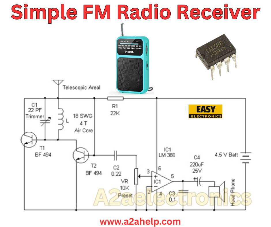
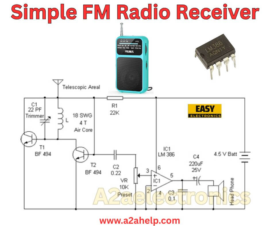
Hey friend, if you have ever wanted to tune into your local FM stations with something you built yourself, this simple FM radio receiver circuit is a fantastic place to start. I have tinkered with radio projects for years as an electronics engineer, and designs like this one bring back memories of my first experiments. The schematic in the image, which looks like it’s from a2aelectronics or a similar source on www.a2ahelp.com, uses just a handful of components to pick up FM signals, demodulate them, and amplify the audio. It runs on a low 4.5V battery, making it portable and easy to power with three AA cells. In this guide, I will analyze the circuit step by step, list the parts you need, show you how to build it, and share some practical tips. Whether you are a beginner or just looking for a quick weekend project, this receiver can deliver clear sound through headphones. Let’s break it down.
Why Build a Simple FM Radio Receiver?
First off, why bother with a DIY radio when you can buy one cheaply? For me, it is about understanding how radio waves turn into music or talk shows. This circuit teaches you the basics of RF tuning, detection, and audio amplification without overwhelming complexity. It is great for educational purposes, like showing kids how electronics work, or for emergency use, where you need to catch news broadcasts off-grid. I have used similar setups during power outages or hikes to stay connected. Plus, it is inexpensive—probably under $10 in parts—and you can customize it, maybe adding a speaker or better antenna. The design here focuses on the FM band (around 88-108 MHz), which is full of stations in most areas. If you live in a city, you will pick up signals easily; in rural spots, a longer antenna helps.
Analyzing the Simple FM Radio Receiver Circuit
Looking closely at the schematic, this is a superheterodyne-inspired design but simplified to the essentials. It starts with the antenna and ends with audio output, with stages for tuning, amplification, detection, and final audio boost. Here is how it flows.
The telescopic aerial picks up FM signals from the air. It connects to a tuning circuit made of C1 (a 22 pF trimmer capacitor) and L (an air-core coil of 18 SWG wire with 4 turns). This LC tank circuit resonates at FM frequencies. By adjusting the trimmer, you tune to different stations—think of it like dialing in on an old radio knob, but here it is a tiny screwdriver adjustment. The coil is air-core, so no ferrite is needed, keeping it light.
Next, transistor T1 (BF494) acts as an RF amplifier. It boosts the weak signal from the antenna. The BF494 is a high-frequency NPN transistor perfect for VHF/UHF work, with good gain up to 500 MHz. R1 (22K) biases it properly, setting the operating point for low noise.
Then comes T2 (another BF494), configured as a detector or demodulator. It extracts the audio from the FM carrier. C2 (0.22 μF, I assume ceramic) couples the signal between stages, blocking DC while passing AC. VR (10K preset) is a variable resistor that fine-tunes the bias or gain, helping with sensitivity or reducing distortion.
The demodulated audio goes to IC1, the LM386. This is a popular low-power audio amplifier IC that can drive headphones or a small speaker directly. It is set up in a basic configuration: Pin 3 is input, pin 5 is output, with C3 (0.1 μF) as a bypass capacitor to stabilize the gain, and C4 (220 μF, 25V electrolytic) coupling the output to the headphones. The power supply is 4.5V from a battery, connected to pin 6 (Vcc) and pin 4 (ground). The LM386 provides about 20 dB gain here, enough for clear listening without external amps.
One thing I notice: There is no explicit IF stage or mixer, so this is more of a tuned RF (TRF) receiver with slope detection for FM. Slope detection uses the side of the tuning curve to demodulate, which is simple but can be less selective than full superhet designs. That means it might pick up strong stations well but struggle with weak ones or interference. Still, for a minimal parts count, it is impressive. The whole circuit draws low current, maybe 10-20 mA, so battery life is decent.
If I were to simulate this, I would expect the tuning range to cover most of the FM band with that 4-turn coil—roughly 5-10 cm diameter if wound on a form like a pencil. Calculations: Inductance L ≈ (turns² * radius²) / (9radius + 10length), but in practice, you tweak the trimmer. The BF494s handle the high frequencies, and the LM386 keeps the audio clean.

Key Components for Your Build
Gather these before starting. I have added notes on where to source them—online shops like Digi-Key or local electronics stores.
- Antenna: Telescopic type, extendable to 50-100 cm for better reception. About $2.
- Capacitors: C1: 22 pF variable trimmer (for tuning). C2: 0.22 μF ceramic. C3: 0.1 μF ceramic. C4: 220 μF electrolytic, 25V rated.
- Inductor: L: 4 turns of 18 SWG (about 1 mm diameter) enameled copper wire, air-core. Wind it yourself on a 1 cm form.
- Resistors: R1: 22K (1/4 watt). VR: 10K preset potentiometer.
- Transistors: T1 and T2: BF494 (NPN RF transistors). Alternatives like BF199 if unavailable.
- IC: LM386 (audio amp, DIP-8 package).
- Power: 4.5V battery holder with three AA cells.
- Output: Headphone jack or small earphones.
- Misc: Perfboard, wires, soldering iron, multimeter. Optional: Small enclosure for portability.
The total cost is low, and most parts are common. If you cannot find BF494, check datasheets for pin-compatible RF transistors with similar ft (transition frequency).
Step-by-Step Guide to Building the Receiver
Let’s assemble it. I recommend breadboarding first to test, then soldering on a perfboard for permanence.
- Prepare the Tuning Section: Wind the coil L—4 tight turns on a non-metallic form, space them slightly if needed. Connect one end to the antenna, the other to T1’s collector. Parallel C1 across L.
- Wire the RF Stage: For T1 (BF494): Emitter to ground, base to the junction of L and C1 (via a small coupling if needed, but direct in the schematic), collector to R1 (22K), which goes to Vcc (4.5V).
- Add the Detector: T2 (BF494): Base connects to T1’s collector via C2 (0.22 μF). Emitter to ground through VR (10K preset). Collector to Vcc.
- Integrate the Audio Amp: IC1 LM386: Pin 1 and 8 open (default gain). Pin 2 to ground via C3 (0.1 μF). Pin 3 (input) to T2’s emitter (adjusted by VR). Pin 4 to ground. Pin 6 to Vcc. Pin 5 (output) to C4 (220 μF), then to headphones. The other headphone leads to ground.
- Power and Antenna: Connect the 4.5V battery. Attach the telescopic antenna.
- Initial Testing: Power on—no smoke? Good. Adjust the trimmer C1 slowly while near an FM transmitter or station. Use the preset VR to peak the audio. You should hear the stations. If static only, check connections or extend the antenna.
- Troubleshooting Basics: No sound? Measure voltages—T1 collector around 2-3V, LM386 pin 5 swinging with audio. Distortion? Tweak VR. Weak signals? Better antenna or location.
- Finishing Touches: Mount in a small plastic box with holes for antenna and headphones. Add a power switch to save battery.
This build takes an hour or two. I built one last year and was surprised how well it pulled in local rock stations.
How This FM Receiver Performs
In real use, expect to tune 5-10 stations depending on your area. Audio quality is mono and basic—good for voice, okay for music. Range is line-of-sight, maybe 10-20 km from transmitters. Battery lasts 10-20 hours. Compared to modern digital radios, it is noisy, but that is the charm. Upgrades: Add a 10K pot for volume before LM386, or a small speaker (8 ohm) with higher supply voltage (up to 9V for LM386).
Common Problems and Fixes
Issues happen. Here are fixes from my experience:
- No Reception: Antenna too short—extend it. Or coil wound wrong—check turns.
- Humming Noise: Ground loops—ensure a single ground point. Or battery low—replace.
- Drift in Tuning: Temperature changes affect the trimmer—use a stable capacitor.
- Overload from Strong Signals: Add a series resistor to the antenna.
- IC Heating: LM386 gets warm; okay, but add a heatsink if using a speaker.
Always test with headphones first to avoid loud surprises.
Safety Considerations
Low voltage here, so minimal risk, but solder carefully to avoid shorts. Batteries can leak, so use fresh ones. If adding a speaker, watch the current draw. For kids, supervise to prevent swallowing small parts.
Why Choose DIY Over Store-Bought?
Building teaches RF basics you will not get from apps. It is customizable—want stereo? Add another channel. Cost-effective, and fun to debug. In my workshop, these projects spark ideas for bigger things like transmitters.
Final Thoughts
There you go, friend—a full guide to this simple FM radio receiver. From the BF494 RF stages to the LM386 audio, it is a clever, minimal design that works. Build it, tune in, and enjoy the satisfaction. For more circuits, check other posts on a2ahelp.com, like amplifiers or inverters. If you tweak it, let me know how it goes. Happy building!

