Introduction to Viper22A SMPS Circuit
The Viper22A is a popular integrated circuit (IC) from STMicroelectronics, widely used in Switch-Mode Power Supply (SMPS) designs. Known for its efficiency and compact design, the Viper22A IC is ideal for low-power applications such as chargers, LED drivers, and small appliances. In this article, we’ll analyze a typical Viper22A SMPS circuit, break down its components, and explain how to build an efficient power supply using this IC. Whether you’re an electronics hobbyist or a professional engineer, this guide will help you understand and implement the Viper22A SMPS circuit for your projects.
What is the Viper22A IC?
The Viper22A is a high-voltage converter IC that integrates a PWM controller and a 730V MOSFET in a single package. It operates in a flyback topology, making it suitable for isolated and non-isolated power supplies. With a built-in startup circuit and protection features like overcurrent and overvoltage protection, the Viper22A simplifies SMPS design while ensuring reliability.
Analyzing the Viper22A SMPS Circuit
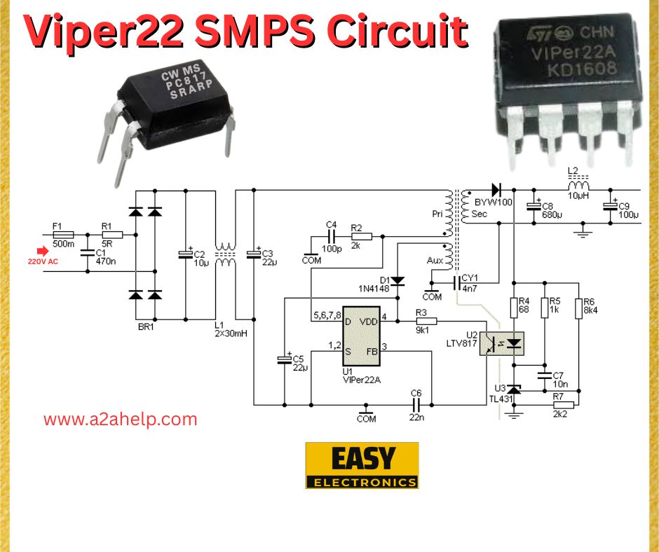
Let’s break down the Viper22A SMPS circuit shown in the schematic above, which is designed to convert 230V AC to a stable DC output.
Key Components and Their Roles
- Input Stage (AC to DC Conversion):
- F1 (500mA Fuse): Protects the circuit from overcurrent conditions.
- BR1 (Bridge Rectifier): Converts the 230V AC input to pulsating DC.
- C1 (470nF), C2 (10µF): Filter capacitors to smooth the rectified DC voltage.
- Viper22A IC (U2):
- The heart of the circuit, Viper22A (U2) handles switching and regulation. It uses pins like VDD, FB (feedback), and S (source) to control the power supply operation.
- D3 (1N4148), C5 (22nF): Form a snubber network to reduce voltage spikes across the IC.
- Transformer (T1):
- The transformer isolates the input and output stages while stepping down the voltage.
- Primary Winding (2x30mH): Connected to the Viper22A’s drain pin.
- Secondary Winding: Provides the output voltage, rectified by D4 (BYW100).
- Auxiliary Winding: Powers the Viper22A via D1 (1N4148) and C3 (10µF).
- Output Stage:
- D4 (BYW100), C8 (680µF), C9 (100µF): Rectify and filter the output voltage to provide a stable DC output.
- L2 (10µH): An output inductor to further reduce ripple.
- Feedback Loop:
- U3 (TL431), R7 (2kΩ), R4 (68Ω), R5 (1kΩ), R6 (8kΩ): The TL431 acts as a voltage reference, providing feedback to the Viper22A via an optocoupler (U1, LTV817).
- This feedback ensures the output voltage remains stable under varying load conditions.

Circuit Operation
The circuit operates as a flyback converter. The Viper22A switches the primary winding of the transformer, storing energy during the ON cycle and transferring it to the secondary during the OFF cycle. The feedback loop adjusts the duty cycle to maintain a constant output voltage, typically around 5V to 12V, depending on the transformer design and component values.
Benefits of Using Viper22A in SMPS Designs
- Efficiency: The Viper22A’s integrated MOSFET and PWM controller reduce power losses.
- Compact Design: Fewer external components are needed, making it ideal for space-constrained applications.
- Cost-Effective: The IC’s low cost and minimal component count reduce overall project expenses.
- Reliability: Built-in protections ensure safe operation under fault conditions.
How to Build a Viper22A SMPS Circuit
- Gather Components: Source all components as per the schematic, ensuring the transformer matches your desired output voltage.
- PCB Design: Lay out the circuit on a PCB, keeping high-voltage traces short and ensuring proper isolation between primary and secondary sides.
- Assemble and Test: Solder the components, double-check connections, and test the circuit with a low load. Monitor the output voltage using a multimeter.
- Safety Precautions: Work with high-voltage AC requires caution. Use proper insulation and test in a controlled environment.
Applications of Viper22A SMPS Circuit
- Chargers: For smartphones, laptops, and other portable devices.
- LED Drivers: Powering LED strips or bulbs.
- Home Appliances: Small appliances like routers, modems, and smart devices.
- Industrial Use: Low-power supplies for sensors and control systems.
Troubleshooting Tips
- No Output Voltage: Check the fuse, bridge rectifier, and Viper22A’s VDD voltage (should be around 14V).
- Unstable Output: Inspect the feedback loop, particularly the TL431 and optocoupler.
- Overheating: Ensure the snubber network (D3, C5) is functioning and the transformer isn’t saturating.
Conclusion
The Viper22A SMPS circuit is a reliable and efficient solution for low-power applications. Its simplicity, combined with the Viper22A IC’s robust features, makes it a go-to choice for electronics engineers and hobbyists alike. By following the schematic and guidelines above, you can build your own SMPS circuit for various projects. For more electronics tutorials and circuit designs, visit [YourWebsiteName]!
