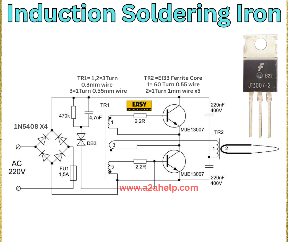
Welcome to Easyelectronics, your go-to destination for innovative electronics projects! Today, we’re exploring the fascinating world of induction soldering irons. This article breaks down the circuit diagram provided, offering a step-by-step analysis and guide to building your own. Whether you’re a hobbyist or a professional, this guide will help you master induction soldering with ease.
What is an Induction Soldering Iron?
An induction soldering iron uses electromagnetic induction to heat the soldering tip, providing a fast, efficient, and contactless heating method. Unlike traditional soldering irons, this design eliminates the need for a heating element, making it a popular choice for precision work. The circuit diagram from Easyelectronics showcases a practical and affordable way to create one.
Analyzing the Induction Soldering Iron Circuit
Let’s dive into the components and workings of this induction soldering iron circuit.

Key Components
- Input (AC 220V): The power source, protected by a 1.5A fuse (FU1).
- Diode Bridge (1N5408 x4): Converts AC to DC, forming a full-wave rectifier.
- Resistor (47kΩ) and Capacitor (4.7nF): Forms a filter network to stabilize the input.
- Transistors (MJE13007): Two transistors drive the oscillation circuit, generating the high-frequency current needed for induction.
- Resistors (2.2Ω): Limit current to the transistors, ensuring safe operation.
- Capacitors (220nF 400V): Part of the resonant circuit, tuning the frequency for induction.
- Transformers (TR1 and TR2):
- TR1: 3-turn primary with 0.3mm wire, 1-turn secondary with 0.55mm wire.
- TR2: E13 ferrite core, 1-60 turns with 0.55mm wire, 2-1 turn with 1mm wire x5.
- Diode (D3): Protects the circuit by preventing reverse voltage.
How It Works
- The AC input is rectified by the diode bridge, producing DC voltage.
- The resistor-capacitor network filters the DC, while the transistors (MJE13007) create a high-frequency oscillating current.
- This current flows through the transformers (TR1 and TR2), generating an electromagnetic field.
- The soldering tip, placed within this field, heats up due to induction, ready for soldering.
Benefits of an Induction Soldering Iron
- Rapid Heating: Heats up instantly, saving time.
- Energy Efficient: No constant heating element, reducing power consumption.
- Durability: Contactless heating minimizes wear on the tip.
- Precision: Ideal for delicate electronic soldering tasks.
Step-by-Step Guide to Building Your Induction Soldering Iron
- Gather Materials: Collect diodes, transistors, resistors, capacitors, transformers, and a fuse as per the diagram.
- Assemble the Circuit: Wire the diode bridge, filter network, and transistor oscillator carefully. Ensure proper transformer winding.
- Test the Setup: Connect to a 220V AC source and test with a non-conductive soldering tip.
- Fine-Tune: Adjust the transformer turns or capacitor values if the heating is inconsistent.
Conclusion
Building an induction soldering iron is a rewarding project that combines creativity with practical electronics knowledge. The circuit from Easyelectronics offers a solid foundation to get started. Explore our site for more DIY ideas and expert guidance. Start soldering smarter today!
