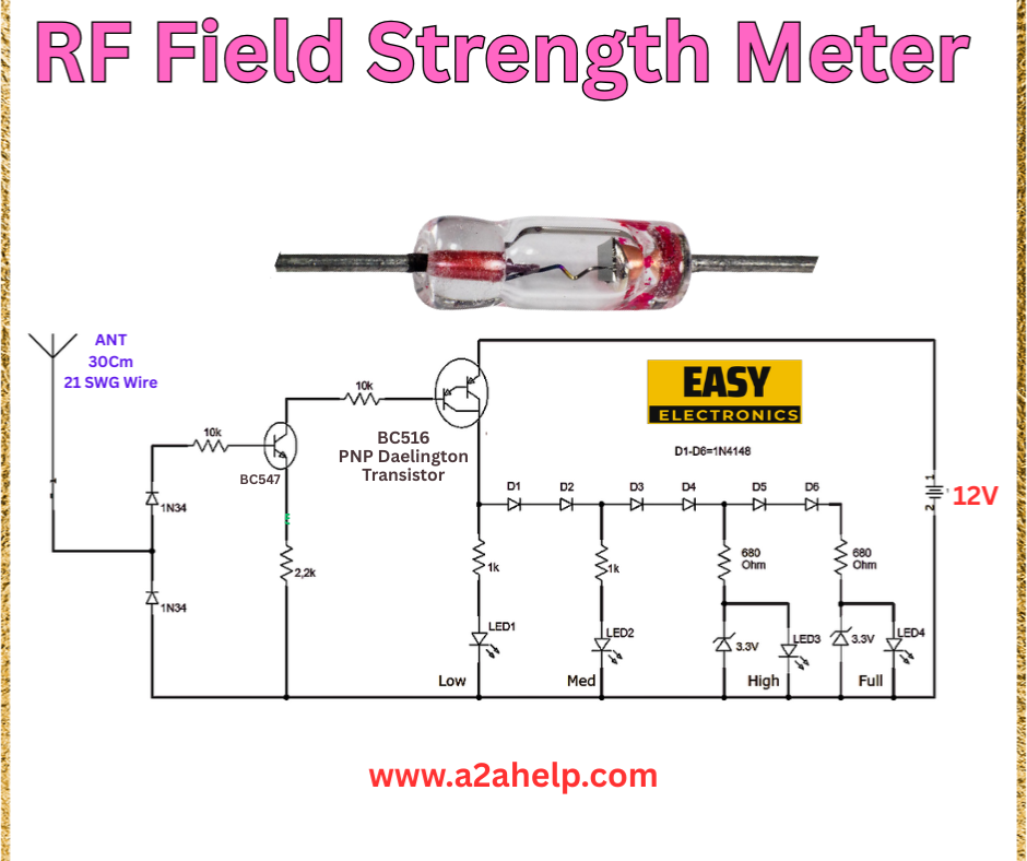
Are you fascinated by radio frequency (RF) signals and want to measure their strength? Building an RF field strength meter is an exciting electronics project that allows you to detect and analyze RF signals in your environment. This step-by-step guide uses a BC516 Darlington transistor and simple components to create a functional meter. Perfect for hobbyists and electronics enthusiasts, let’s explore how to build this device today!
What Is an RF Field Strength Meter?
An RF field strength meter is a tool used to measure the intensity of radio frequency electromagnetic fields. This DIY version uses a diode detector and a series of LEDs to indicate signal strength across different levels (Low, Medium, High, Full). It’s an excellent project for learning about RF detection, transistor circuits, and signal processing.
Materials Needed
Gather the following components to get started:
- BC516 PNP Darlington Transistor
- 1N34 Diode (x2)
- 10kΩ Resistor
- 2.2kΩ Resistor
- 1kΩ Resistor (x2)
- 680Ω Resistor (x2)
- LED (x4)
- Antenna (30cm, 21 SWG wire)
- 12V Power Supply
- Breadboard or PCB
- Connecting wires
Circuit Diagram Explanation
The circuit diagram is designed for simplicity and effectiveness. Here’s a breakdown of the connections:
- Antenna: A 30cm 21 SWG wire captures RF signals.
- BC516 Transistor: Acts as a high-gain amplifier for the detected signal.
- Diodes and Resistors: The 1N34 diodes detect RF, while resistors set bias and current limits.
- LEDs: Indicate signal strength with four levels (Low, Med, High, Full).
- Power Supply: A 12V source powers the circuit.

Step-by-Step Guide to Building the RF Field Strength Meter
Step 1: Prepare the Breadboard
Place the BC516 transistor on the breadboard. Identify the emitter (E), base (B), and collector (C) pins based on the datasheet.
Step 2: Connect the Antenna
Attach a 30cm 21 SWG wire as the antenna to the circuit’s input point, connected to the first 1N34 diode.
Step 3: Set Up the Detector Stage
- Connect the first 1N34 diode between the antenna and the base of the BC516 transistor.
- Add a second 1N34 diode in series with a 10kΩ resistor, linking it to the base.
- Connect a 2.2kΩ resistor between the base and ground.
Step 4: Configure the Amplifier
- Link the emitter of the BC516 to ground.
- Connect the collector to the 12V supply through a 1kΩ resistor.
Step 5: Add the LED Indicators
- Connect a 1kΩ resistor from the collector to the anode of the first LED (Low).
- Link the cathode of the first LED to the anode of the second LED (Med) with a 680Ω resistor.
- Continue this chain with the third LED (High) and fourth LED (Full), each with a 680Ω resistor.
- Ensure the cathode of the last LED is grounded.
- Adjust the voltage drop across each LED (e.g., 3.3V) for accurate indication.
Step 6: Power and Test
Connect the 12V power supply. Move the antenna near an RF source (e.g., a radio transmitter). The LEDs should light up based on signal strength: one for Low, two for Medium, three for High, and all four for Full.
How Does It Work?
The antenna picks up RF signals, which are rectified by the 1N34 diodes. The BC516 Darlington transistor amplifies the detected signal. The amplified voltage drives the LED chain, with each LED lighting up as the signal strength increases. Resistors limit current to protect the LEDs and ensure accurate level indication.
Safety Precautions
- Antenna Placement: Keep the antenna away from high-power RF sources to avoid damage.
- Power Supply: Use a regulated 12V supply to prevent overvoltage.
- Component Handling: Avoid static discharge when working with the transistor.
Troubleshooting Tips
- No LED Response: Check the power supply and antenna connection.
- All LEDs On: Ensure proper resistor values and diode orientation.
- Weak Detection: Extend the antenna or check for interference.
Benefits of Building an RF Field Strength Meter
- Educational: Learn about RF detection and transistor amplification.
- Practical Use: Useful for testing RF devices or locating signal sources.
- Cost-Effective: Relies on affordable, accessible components.
Conclusion
Building an RF field strength meter is a rewarding project that combines RF technology with practical electronics skills. This guide provides all the steps to create a working meter using a BC516 transistor and LEDs. For more innovative electronics projects and tutorials, visit www.a2ahelp.com. Start building and explore the world of RF signals today!
