Hey there! If you’ve ever wanted to convert 12V DC from a battery into 220V AC for powering household devices, an inverter circuit is your answer. Today, I’m excited to walk you through building one using the SG3525 IC. It’s a fun project that’s perfect if you’re into electronics and want to try something practical. Let’s get started!
What is an Inverter Circuit?
An inverter circuit takes a low DC voltage, like 12V from a car battery, and turns it into a higher AC voltage, such as 220V. The SG3525 is a pulse-width modulation (PWM) controller that makes this process efficient and reliable. It’s great for powering small appliances or learning more about power electronics.
What You’ll Need
Here’s what you’ll need to put this together:
- SG3525 IC: The brain of the circuit, handling PWM.
- IRF3205 MOSFETs (2): These switch the current to drive the transformer.
- 12V Battery: Your power source.
- 220V to 12V Transformer: Used in reverse to step up voltage.
- Resistors: 12kΩ (R9), 22Ω (R10), 1kΩ (R11), 2kΩ (R14), 120kΩ (R13), 470kΩ (R12).
- Capacitors: 1nF (C5), 22µF (C6).
- Potentiometer: 10kΩ (RV1) for adjusting frequency.
- Diodes: 27V Zener (2) for protection.
- Switch: SPST (SW1) to turn it on/off.
- Breadboard and Wires: For assembling the circuit.
- Multimeter: To check your work.

How to Assemble the Circuit
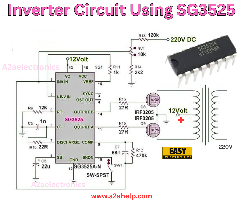
The image gives you a clear layout, so let’s build it step by step:
Step 1: Set Up the SG3525
- Connect pin 1 (INV IN) and pin 2 (NINV IN) to ground through a 12kΩ resistor (R9).
- Link pin 5 (CT) to a 1nF capacitor (C5) to ground, and pin 7 (DISCHARGE COMP) to a 22µF capacitor (C6) to ground.
- Attach pin 15 (VCC) to the 12V supply.
- Connect pin 16 (VREF) to pin 14 (OUTPUT B) and pin 11 (OUTPUT A) through a 1kΩ resistor (R11).
- Use a 2kΩ resistor (R14) and a 10kΩ potentiometer (RV1) between pin 16 and ground to set the frequency.
Step 2: Add the MOSFETs
- Connect the gates of the two IRF3205 MOSFETs to pins 14 and 11 (OUTPUT B and OUTPUT A).
- Link the sources to ground and the drains to the transformer’s primary winding.
- Place a 27V Zener diode across each gate-source to protect the MOSFETs.
Step 3: Wire the Transformer and Power
- Connect the transformer’s primary side to the MOSFET drains and the 12V supply.
- The secondary side will output 220V AC. Be careful here!
- Add a 120kΩ resistor (R13) from the 220V DC line to pin 16 for feedback.
- Use a 470kΩ resistor (R12) and a 68nF capacitor (C7) from the transformer to ground for stability.
- Install the SPST switch (SW1) in the 12V line to control power.
Step 4: Final Checks
- Double-check all connections. Make sure the polarities of capacitors and diodes are correct.
- Ensure the transformer is wired in reverse (12V side to the circuit, 220V side as output).
How It Works
The SG3525 generates PWM signals to control the MOSFETs, which switch the 12V DC through the transformer. This creates an alternating magnetic field, stepping up the voltage to 220V AC on the secondary side. The potentiometer lets you tweak the output frequency, and the Zener diodes protect the MOSFETs from spikes.
Testing and Troubleshooting
- Turn on the switch and listen for a hum from the transformer, indicating it’s working.
- If no output, check the 12V supply, MOSFET connections, and transformer wiring.
- Adjust RV1 if the voltage is unstable. Use a multimeter to confirm 220V AC.
Why This Project is Worth It
This inverter is a solid way to learn about power conversion. It’s efficient, uses common parts, and can power small devices like lights or fans. Plus, it’s a confidence booster for your electronics skills.
Safety Tips
- Handle the 220V output with care to avoid shocks.
- Use insulated tools and work in a dry area.
- Disconnect the battery when not testing.
Wrap-Up
Building an inverter with the SG3525 is a rewarding challenge that opens up new possibilities in electronics. Take your time, follow the steps, and you’ll have a working circuit in no time. For more projects like this, check out www.a2ahelp.com. Let’s keep building and learning together!
