Are you intrigued by high-voltage experiments or looking to power unique electronics projects? A flyback transformer driver is an exciting DIY project that can generate high voltages for applications like Jacob’s ladders or ion generators. In this detailed guide, we’ll walk you through building a simple yet effective flyback transformer driver using accessible components. Perfect for electronics enthusiasts, let’s get started!
What is a Flyback Transformer Driver?
A flyback transformer driver uses a transformer to step up a low-voltage input into a high-voltage output. The flyback mechanism stores energy in the transformer’s magnetic field and releases it as a high-voltage pulse. This circuit is widely used in old CRT televisions, plasma displays, and hobbyist high-voltage projects.
Components You’ll Need
To build this flyback transformer driver, gather the following items:
- 2N3055 Transistor: A robust NPN transistor to drive the circuit.
- Flyback Transformer: With a ferrite core, primary (4-6 turns), and feedback (2-4 turns) windings.
- 240Ω Resistor (5W): Limits current to the transistor.
- 27Ω Resistor (1W): Provides base current.
- Switch: To control power to the circuit.
- Insulating Tape: For safety and securing windings.
- 12V Power Supply: To power the driver.
- Breadboard and Connecting Wires: For assembly.
- Multimeter: To troubleshoot and verify connections.
Circuit Diagram and Assembly
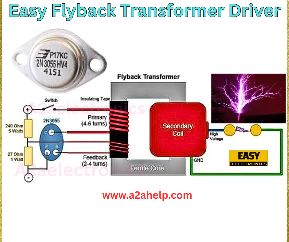
The circuit diagram in the image offers a clear guide for assembling the flyback transformer driver. Follow these steps:

Step 1: Prepare the Flyback Transformer
- Wind 4-6 turns of insulated wire around the primary coil and 2-4 turns for the feedback coil on the ferrite core.
- Secure the windings with insulating tape to prevent short circuits.
- Ensure the secondary coil (high-voltage output) is intact and properly insulated.
Step 2: Connect the Transistor
- Attach the collector (C) of the 2N3055 transistor to the primary coil of the flyback transformer.
- Connect the emitter (E) to ground.
- Link the base (B) to the junction of the 27Ω resistor and the feedback coil.
Step 3: Add Resistors and Power
- Connect the 240Ω resistor between the 12V power supply and the collector.
- Attach the 27Ω resistor from the base to the positive supply via the switch.
- Ground the negative terminal of the power supply and the feedback coil’s end.
Step 4: Final Connections
- Double-check all connections for secure contact.
- Ensure the high-voltage output (secondary coil) is directed to a safe load or experiment setup.
- Insulate exposed wires to avoid shorts.
How It Works
The 2N3055 transistor switches the current through the primary coil, creating a magnetic field in the flyback transformer. When the transistor turns off, the collapsing field induces a high-voltage pulse in the secondary coil. The feedback coil sustains oscillation, enabling continuous high-voltage generation. The resistors limit current to protect the transistor.
Testing and Troubleshooting
- Power On: Flip the switch and observe for high-voltage output (e.g., sparks or glow).
- Check Issues: If no output, verify the transformer windings, transistor orientation, and power supply.
- Adjust: Tweak the feedback coil turns for stable oscillation.
Benefits of a Flyback Transformer Driver
- High Voltage Output: Ideal for educational and experimental projects.
- Simple Design: Uses minimal components.
- Versatile: Applicable in various high-voltage applications.
Safety Tips
- Handle high-voltage outputs with extreme caution to avoid electric shock.
- Use insulated tools and wear protective gear.
- Ensure proper ventilation to dissipate heat from the transistor.
Conclusion
Building a flyback transformer driver is a thrilling way to explore high-voltage electronics and unleash your creativity. With the right components and careful assembly, you can power impressive projects safely. Visit www.a2ahelp.com for more electronics tutorials and inspiration. Start your high-voltage journey today!
