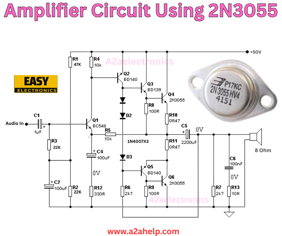
Hey there! If you’re looking to build a solid audio amplifier that can drive an 8-ohm speaker with some real power, this circuit using the 2N3055 transistor is a great option. It’s a classic design that’s been around for years, and it’s perfect for learning about transistor amplification stages. The whole thing runs on a single 50V supply and delivers decent output for small audio projects. Let’s walk through it together.
What is This Amplifier Circuit?
This is a class AB audio amplifier built around the 2N3055 power transistor. It takes a low-level audio input, like from a phone or preamp, and boosts it to drive a speaker. The design uses a few stages: a preamp for initial gain, drivers for control, and power transistors for the heavy lifting. It’s efficient enough for home use and teaches you about biasing and heat management.
What You’ll Need
Here’s the list of components based on the diagram:
- Transistors: Q1 (BC546), Q2 (BD140), Q3 (BD139), Q4 (2N3055), Q5 (BD140), Q6 (2N3055)
- Diodes: D1 (BD140? Wait, no—D1, D2, D3 are 1N4007 or similar)
- Capacitors: C1 (1µF), C2 (100µF), C4 (100µF), C5 (0V? Looks like a label error, probably a bypass), C6 (100nF)
- Resistors: R1 (47k), R2 (22k), R3 (22k), R4 (10k), R6 (27Ω), R7 (1k? Wait, R7 27Ω), R8 (100Ω), R9 (10Ω), R10 (47Ω), R12 (330Ω), R13 (10Ω)
- Other: Audio input jack, 8-ohm speaker, +50V power supply, heat sinks for the power transistors
- Breadboard or PCB, wires, multimeter
Make sure to get the 2N3055 on a good heat sink because it handles the power.
How to Assemble the Circuit
The diagram shows a clear layout, so let’s build it step by step:

Step 1: Input and Preamp Stage
- Connect the audio input to C1 (1µF), then to the base of Q1 (BC546).
- From Q1’s collector, add R1 (47k) to +50V.
- Emitter of Q1 goes through R3 (22k) to ground.
- Couple the collector of Q1 to the base of Q2 (BD140) via R4 (10k? Wait, direct in diagram).
Step 2: Driver Stage
- Q2 (BD140) collector to base of Q3 (BD139) through D2.
- Add biasing diodes D1, D3 in series for thermal stability.
- Q3 collector to +50V through R8 (100Ω? Labels).
- Emitter of Q3 to base of Q4 (2N3055).
Step 3: Power Stage
- Q4 (2N3055) collector to +50V.
- Emitter to output through R10 (47Ω).
- Mirror for the lower half: Q5 (BD140), Q6 (2N3055) for push-pull.
- Output to speaker via C6 (100nF? No, direct to 8 ohm).
Step 4: Add Filtering and Power
- Place C2 (100µF) and C4 (100µF) for supply decoupling.
- Connect the +50V supply and ground as shown.
- Check transistor pins: base, collector, emitter for each.
Take your time with connections to avoid shorts.
How It Works
The audio signal enters at Q1, which provides voltage gain. Q2 and Q3 act as drivers, biasing the power transistors Q4 and Q6 in a Darlington-like setup for high current gain. The diodes help with quiescent current to reduce crossover distortion in class AB mode. The output stage pushes and pulls current through the speaker, amplifying the signal. Resistors set bias and limit current, while capacitors filter noise.
Testing and Troubleshooting
- Power up without input and check DC at the output—it should be near 0V.
- Input a low audio signal and listen on the speaker.
- If distorted, adjust bias resistors or check for oscillation with a scope.
- Measure heat on the 2N3055; if too hot, add better cooling.
Why This Project is Worth It
This circuit is a staple for understanding power amps. It’s cheap, uses common parts, and you can scale it for more power with a higher supply. Plus, it’s satisfying to hear your music through something you built.
Safety Tips
- 50V can bite, so disconnect power when working.
- Use heat sinks to prevent transistor burnout.
- Work in a vented area if soldering.
Wrap-Up
The 2N3055 amplifier is a reliable choice for any electronics enthusiast. Give it a try, and you’ll learn a ton. For more ideas, visit www.a2ahelp.com. Tell me how it goes!
