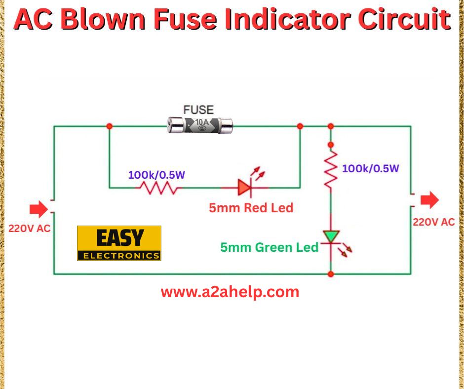
If you’ve ever dealt with a blown fuse in an AC circuit and struggled to identify the issue quickly, an AC blown fuse indicator circuit is a game-changer. This simple yet effective DIY project uses basic electronic components to alert you when a fuse fails. In this article, we’ll walk you through the design, assembly, and functionality of an AC blown fuse indicator circuit based on the schematic provided. Perfect for hobbyists and professionals alike, this guide will help you enhance your electrical troubleshooting skills. Let’s get started!
What Is an AC Blown Fuse Indicator Circuit?
An AC blown fuse indicator circuit is a diagnostic tool that visually signals when a fuse in a 220V AC line has blown. By using LEDs, this circuit provides an immediate indication—green for a working fuse and red for a blown one—saving you time and effort. This is especially useful in home appliances, industrial equipment, or any system relying on fuse protection.
Components Required
To build this AC blown fuse indicator circuit, gather the following:
- Fuse (10A): The protective component to be monitored.
- Resistors (100kΩ, 0.5W): Two resistors for current limiting.
- 5mm Red LED: Indicates a blown fuse.
- 5mm Green LED: Indicates a functioning fuse.
- 220V AC Power Source: The main supply line.
- Breadboard and Wires: For prototyping and connections.
- Enclosure (Optional): For safe and permanent installation.
Circuit Diagram Analysis

The schematic shows a straightforward design:
- The 10A fuse is placed in the 220V AC line, protecting the circuit from overcurrent.
- A 100kΩ, 0.5W resistor is connected in series with the 5mm red LED, which lights up when the fuse blows, completing the circuit across the AC line.
- Another 100kΩ, 0.5W resistor is in series with the 5mm green LED, which glows when the fuse is intact, allowing current to flow through the LED path.
- The LEDs are connected in parallel across the fuse, with opposite polarities to detect the AC voltage direction.
Step-by-Step Assembly Guide
- Set Up the Breadboard: Prepare your breadboard and ensure all connections are secure.
- Install the Fuse: Place the 10A fuse in the 220V AC line as the first component.
- Connect the Red LED Circuit: Attach the 100kΩ resistor to one side of the fuse, then connect the 5mm red LED in series. The other end of the LED connects to the opposite side of the fuse.
- Connect the Green LED Circuit: Link the second 100kΩ resistor to the fuse’s input side, followed by the 5mm green LED, with its other end tied to the output side of the fuse.
- Verify Polarity: Ensure the LEDs are oriented correctly based on the AC polarity (note that AC alternates, so both LEDs may light alternately in a working state).
- Power the Circuit: Connect the 220V AC supply and test the setup.
- Secure the Setup: Use an enclosure if needed, and insulate all exposed wires for safety.
How It Works
This circuit leverages the AC voltage across the fuse. When the fuse is intact, the green LED lights up, indicating normal operation. If the fuse blows, the green LED turns off, and the red LED illuminates by completing the circuit through the AC line. The 100kΩ resistors limit current to a safe level for the LEDs, preventing damage from the 220V supply.
Tips for Success
- Safety First: Always work with 220V AC circuits using proper insulation and disconnect power before adjustments.
- Resistor Rating: Use 0.5W resistors to handle the voltage drop safely.
- LED Brightness: If LEDs are dim, verify resistor values or AC voltage.
- Testing: Use a multimeter to confirm fuse status before relying solely on the indicator.
Applications of the AC Blown Fuse Indicator
- Home Appliances: Monitor fuses in washing machines, refrigerators, or air conditioners.
- Industrial Equipment: Ensure continuous operation in machinery with critical fuse protection.
- DIY Projects: Add this circuit to custom electronics for added functionality.
Troubleshooting Common Issues
- Both LEDs Off: Check for loose connections or a faulty power supply.
- Red LED Always On: The fuse may already be blown; replace and retest.
- Green LED Dim: Ensure correct resistor value and AC supply stability.
Conclusion
Building an AC blown fuse indicator circuit is a practical and educational project for anyone interested in electronics. With just a few components and this step-by-step guide, you can create a reliable tool to detect fuse failures instantly. For more electronics tutorials and projects, visit www.a2ahelp.com. Share your experience in the comments below—we’d love to hear how it went!
