Are you an electronics enthusiast looking to test Zener diodes with precision? A Zener diode tester is an essential tool for verifying the breakdown voltage of Zener diodes, ensuring your circuits perform optimally. In this detailed guide, we’ll walk you through building your own Zener diode tester using simple components. Perfect for hobbyists and professionals alike, this DIY project will enhance your electronics skills. Let’s get started!
What is a Zener Diode Tester?
A Zener diode tester is a circuit designed to measure the reverse breakdown voltage of a Zener diode, a special type of diode that allows current to flow in the reverse direction when a specific voltage is reached. This tester uses a digital voltmeter to display the Zener voltage accurately, making it a handy tool for troubleshooting and component testing.
Components Required
To build this Zener diode tester, gather the following materials:
- BC547 Transistor (1 piece)
- BC549C Transistor (1 piece)
- 470Ω Resistor (R4)
- 1kΩ Resistors (R1, R2, R3)
- Switches (SW1, SW2, SW3)
- Digital Voltmeter
- 24V Power Supply
- Zener Diode (for testing)
- Connecting Wires
Understanding the Circuit Diagram
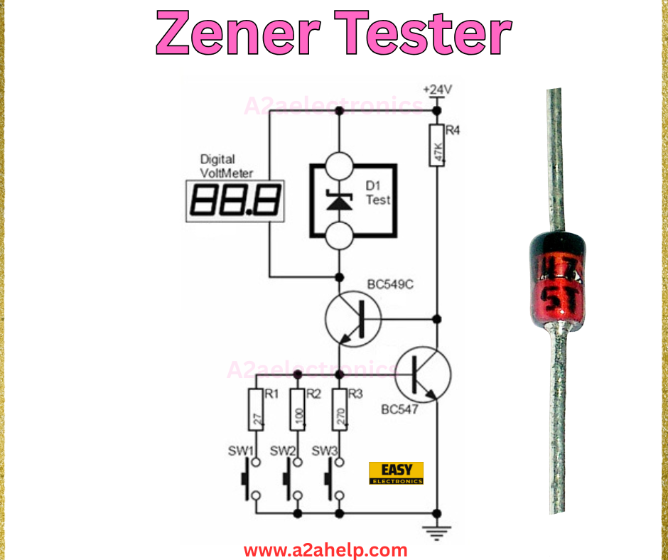
The circuit diagram illustrates a straightforward design. Here’s a breakdown of the components and their roles:

- BC547 and BC549C Transistors: These NPN transistors form a current-regulating pair, ensuring stable operation.
- Resistors (R1, R2, R3): These 1kΩ resistors limit the base current to the transistors.
- Resistor (R4): The 470Ω resistor protects the Zener diode by limiting current.
- Switches (SW1, SW2, SW3): These allow you to control the circuit and select the test mode.
- Digital Voltmeter: Displays the Zener voltage in real-time.
- 24V Power Supply: Provides the necessary voltage to test the Zener diode.
- Zener Diode (D1): The component being tested, connected in reverse bias.
How the Zener Diode Tester Works
The Zener diode tester operates by applying a variable voltage across the diode in reverse bias. Here’s how it functions:
- The 24V power supply provides the input voltage.
- The transistors regulate the current, ensuring the Zener diode operates within safe limits.
- When the reverse voltage reaches the Zener breakdown voltage, the diode conducts, and the digital voltmeter displays the voltage.
- Switches (SW1, SW2, SW3) allow you to adjust the circuit for different Zener voltage ranges.
This setup ensures accurate measurement and protects the diode from damage due to excessive current.
Step-by-Step Guide to Build the Circuit
Step 1: Gather Materials
Collect all the components listed above. You can find them at local electronics stores or online retailers.
Step 2: Assemble the Circuit
- Connect the emitter of the BC547 transistor to the ground.
- Link the collector of BC547 to the base of BC549C.
- Attach the 1kΩ resistors (R1, R2, R3) between the power supply and the transistor bases.
- Connect the 470Ω resistor (R4) in series with the Zener diode (D1).
- Place the Zener diode in reverse bias across the circuit.
- Integrate the digital voltmeter to measure the voltage across D1.
- Add switches (SW1, SW2, SW3) to control the power and test modes.
- Connect the 24V power supply to the circuit.
Step 3: Test the Circuit
Power on the circuit and insert a Zener diode into the test slot. Adjust the switches and observe the voltmeter reading. The displayed value should match the Zener diode’s specified breakdown voltage.
Step 4: Secure the Setup
Once tested, secure the connections and housing to ensure safety and durability. Label the switches for easy operation.
Advantages of a Zener Diode Tester
- Accuracy: Provides precise voltage readings.
- Cost-Effective: Uses affordable, readily available components.
- Portable: Compact design for easy use.
- Versatile: Suitable for testing various Zener diodes.
Troubleshooting Tips
- No Voltage Reading: Check the power supply and ensure proper connections.
- Inaccurate Readings: Verify the Zener diode orientation and resistor values.
- Overheating: Reduce the input voltage or check for short circuits.
Applications
This Zener diode tester is ideal for:
- Electronics repair shops
- Educational labs
- DIY electronics projects
- Quality control in manufacturing
Conclusion
Building a Zener diode tester is a valuable project that combines practical electronics knowledge with hands-on experience. By following this guide, you can create a reliable tool to test Zener diodes effectively. Whether you’re a beginner or an expert, this circuit will enhance your troubleshooting capabilities. Try it out today and share your feedback with us!
For more electronics projects and tutorials, visit www.a2ahelp.com. Got questions? Drop a comment below!
