Introduction to Soldering Iron Temperature Control
Soldering irons are essential tools for electronics enthusiasts and professionals alike. However, maintaining the right temperature is crucial to ensure precise soldering without damaging components. In this guide, we’ll explore a simple yet effective soldering iron temperature control circuit using a TRIAC (BT136) that allows you to adjust the heat output for optimal performance. This DIY project is perfect for hobbyists looking to enhance their soldering experience with a custom temperature control solution.
Understanding the Soldering Iron Temperature Control Circuit
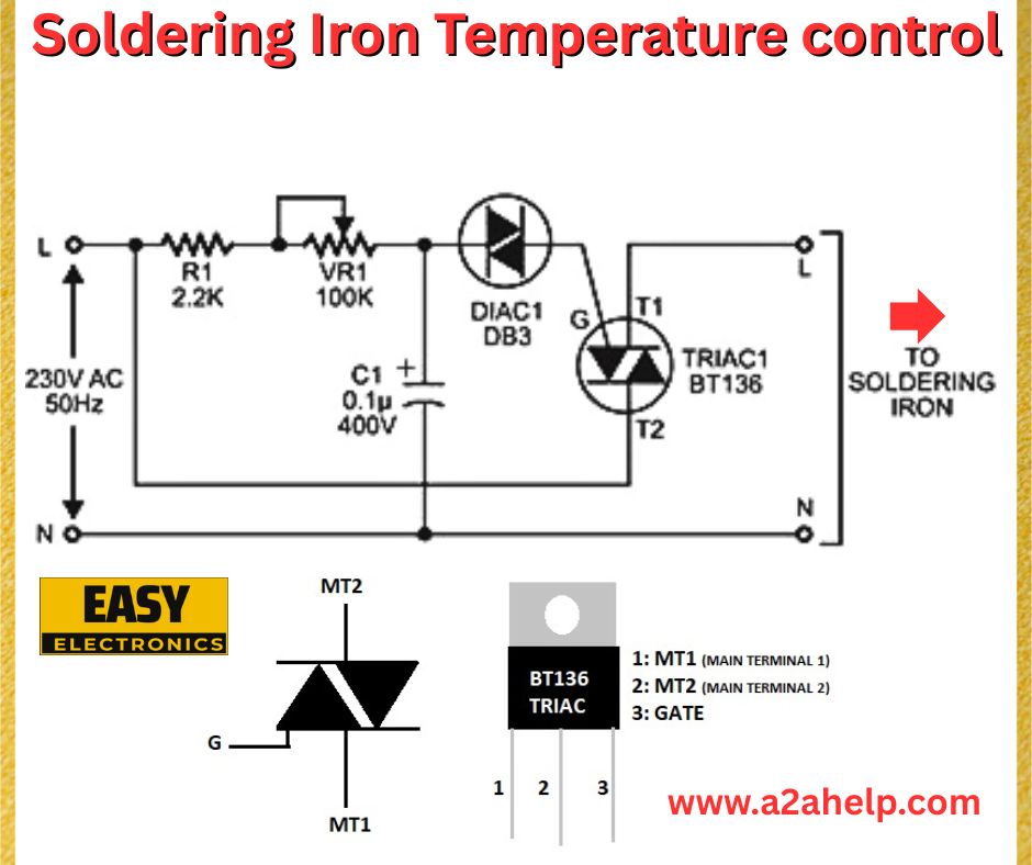
The circuit diagram shown below provides a reliable way to control the temperature of a soldering iron by regulating the AC power supplied to it. This design uses a TRIAC-based phase control method, which is both cost-effective and efficient for adjusting the power delivered to the soldering iron.
Key Components:
- TRIAC (BT136): A semiconductor device used to control the AC power to the soldering iron.
- DIAC (DB3): Triggers the TRIAC by providing a sharp voltage pulse.
- Variable Resistor (VR1, 100K): Adjusts the firing angle of the TRIAC to control power output.
- Resistor (R1, 2.2K): Limits the current in the circuit.
- Capacitor (C1, 0.1µF, 400V): Works with the variable resistor to set the TRIAC’s firing delay.
- AC Supply (230V, 50Hz): Powers the circuit and the soldering iron.
How the Soldering Iron Temperature Control Circuit Works
The circuit operates on the principle of phase control. The 230V AC supply is fed into the circuit, where the TRIAC (BT136) acts as a switch to control the power delivered to the soldering iron. Here’s a breakdown of the operation:
- Phase Control Mechanism: The variable resistor (VR1) and capacitor (C1) form an RC network that delays the voltage buildup across the DIAC (DB3). By adjusting VR1, you change the timing of the voltage pulse that triggers the DIAC.
- TRIAC Activation: Once the DIAC fires, it sends a pulse to the gate (G) of the TRIAC (BT136), turning it on for a portion of the AC cycle. This controls the amount of power reaching the soldering iron.
- Temperature Adjustment: Increasing the resistance of VR1 delays the TRIAC’s firing, reducing the power to the soldering iron and lowering its temperature. Conversely, decreasing the resistance allows more power, increasing the temperature.
The TRIAC’s terminals (MT1, MT2, and Gate) are connected as shown: MT2 goes to the soldering iron, MT1 to the neutral line, and the gate is triggered by the DIAC.

Step-by-Step Guide to Building the Circuit
Follow these steps to assemble your own soldering iron temperature control circuit:
- Gather Components: Source the components listed above. Ensure the TRIAC (BT136) and capacitor (C1) are rated for at least 400V to handle the 230V AC supply safely.
- Assemble the Circuit: Connect the components as per the schematic:
- Connect the live (L) wire of the 230V AC supply to one end of R1 (2.2K).
- Connect the other end of R1 to the variable resistor (VR1, 100K) and one terminal of the capacitor (C1, 0.1µF).
- Connect the other terminal of C1 to the neutral (N) line and MT1 of the TRIAC.
- Connect the junction of VR1 and C1 to the DIAC (DB3), and the other end of the DIAC to the gate (G) of the TRIAC.
- Connect MT2 of the TRIAC to the soldering iron, and the other terminal of the soldering iron to the neutral line.
- Test the Circuit: Plug the circuit into a 230V AC supply and turn on the soldering iron. Adjust VR1 to control the temperature. The soldering iron should heat up more quickly at lower resistance settings and cool down at higher resistance settings.
- Safety Check: Double-check all connections to ensure there are no loose wires or short circuits. Use a non-conductive enclosure to house the circuit for safe operation.
Advantages of This Temperature Control Circuit
- Cost-Effective: Uses minimal, affordable components.
- Customizable: The variable resistor allows precise temperature adjustments.
- Compact Design: Easy to integrate into a small enclosure for portability.
- Energy Efficient: Reduces power consumption by limiting the energy supplied to the soldering iron when full heat isn’t needed.
Safety Precautions
- High Voltage Warning: This circuit operates on 230V AC, which can be dangerous. Ensure proper insulation and avoid touching live components.
- Component Ratings: Use components rated for the appropriate voltage and current to prevent overheating or failure.
- Grounding: Ensure the soldering iron is properly grounded to avoid electric shock.
Troubleshooting Tips
- Soldering Iron Not Heating: Check the TRIAC and DIAC for proper connections. Ensure the variable resistor is functioning and not set to maximum resistance.
- Unstable Temperature: Verify the capacitor value and ensure there are no loose connections in the RC network.
- Overheating: If the soldering iron gets too hot even at the highest resistance setting, the TRIAC may be faulty and stuck in the “on” state—replace it.
Why Use a TRIAC for Soldering Iron Temperature Control?
TRIACs are ideal for AC power control because they can conduct current in both directions, making them perfect for phase control applications like this one. The BT136 TRIAC is a robust choice, capable of handling the current required by most soldering irons (typically 25-50W). Paired with a DIAC, it provides smooth and reliable temperature regulation.
Conclusion
Building a soldering iron temperature control circuit using a TRIAC (BT136) is a rewarding project for electronics enthusiasts. This simple circuit allows you to fine-tune the temperature of your soldering iron, improving soldering precision and protecting delicate components. By following the steps outlined in this guide, you can create a cost-effective and efficient temperature control solution for your soldering needs.
