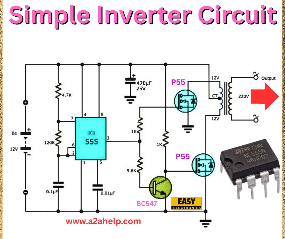
Are you interested in learning how to create your own power backup solution? A simple inverter circuit can convert DC power from a battery into AC power, making it perfect for running small household appliances during power outages. In this detailed guide, we’ll analyze the provided circuit diagram and walk you through the process of building a simple inverter circuit step by step. Ideal for electronics enthusiasts and hobbyists, this tutorial will help you understand the components, assembly, and functionality of the circuit.
Understanding the Simple Inverter Circuit

The circuit diagram above represents a basic inverter that converts 12V DC from a battery into 220V AC. This design uses a 555 timer IC and a few other components to generate a square wave, which is then amplified to produce the required AC output. Let’s dive into the components and their roles in this circuit.
Components Required
- 12V Battery (B1): Provides the input DC voltage.
- 555 Timer IC (IC1): Generates the oscillating signal for the inverter.
- 4.7K and 120K Resistors: Set the frequency of the 555 timer.
- 0.01µF and 0.1µF Capacitors: Stabilize the timer circuit and filter noise.
- 470µF 25V Capacitor: Smooths the DC input.
- 1K and 5.6K Resistors: Control the base current of the transistors.
- BC547 Transistor: Acts as a switching element.
- P55 MOSFETs: Amplify the signal to drive the transformer.
- 12V-220V Step-Up Transformer: Converts the low-voltage AC to 220V AC.
- Heat Sink: Dissipates heat from the MOSFETs.
Circuit Diagram Analysis
- Oscillator Stage: The 555 timer IC, configured in astable mode, generates a square wave. The 4.7K and 120K resistors, along with the 0.01µF capacitor, determine the oscillation frequency (typically around 50-60 Hz for AC compatibility).
- Amplification Stage: The BC547 transistor amplifies the signal from the 555 timer. The 1K and 5.6K resistors control the base current, ensuring proper switching.
- Power Stage: Two P55 MOSFETs act as switches, driven by the amplified signal. They alternate the current through the transformer’s primary winding.
- Output Stage: The step-up transformer boosts the low-voltage AC to 220V AC, which is then available at the output terminals.
Step-by-Step Assembly Guide
- Prepare the 555 Timer Circuit: Connect the 4.7K and 120K resistors, along with the 0.01µF capacitor, to the 555 timer IC pins (as shown in the diagram) to set the oscillation frequency.
- Add the BC547 Transistor: Solder the BC547 transistor, connecting its base to pin 3 of the 555 timer via the 1K resistor and its collector to the 5.6K resistor.
- Install the MOSFETs: Attach the P55 MOSFETs to a heat sink. Connect their gates to the transistor’s collector and emitter, ensuring proper polarity.
- Connect the Capacitors: Solder the 470µF capacitor across the battery terminals for smoothing and the 0.1µF capacitor for noise suppression.
- Wire the Transformer: Link the MOSFETs to the primary winding of the 12V-220V step-up transformer. Connect the secondary winding to the output terminals.
- Test the Circuit: Before powering on, verify all connections with a multimeter. Apply 12V DC and check the output with an AC voltmeter.
Working Principle
The 555 timer generates a square wave that toggles the BC547 transistor on and off. This signal drives the P55 MOSFETs, which alternately switch the current through the transformer’s primary coil. The transformer steps up the voltage from 12V AC to 220V AC, providing a usable AC output. The capacitors ensure stability and reduce noise in the circuit.
Safety Tips
- Use a heat sink with the MOSFETs to prevent overheating.
- Ensure proper insulation to avoid electrical shocks.
- Test the circuit with a low load initially to confirm safe operation.
Applications
This simple inverter circuit is suitable for powering small devices like LED lights, fans, or chargers during power cuts. It’s an excellent project for learning about power electronics and backup systems.
Conclusion
Building a simple inverter circuit is a fantastic way to gain hands-on experience in electronics. By following this guide and using the provided diagram, you can create a reliable 12V to 220V inverter for your needs. For more electronics projects and tutorials, visit www.a2ahelp.com. Have any questions? Drop a comment below!
