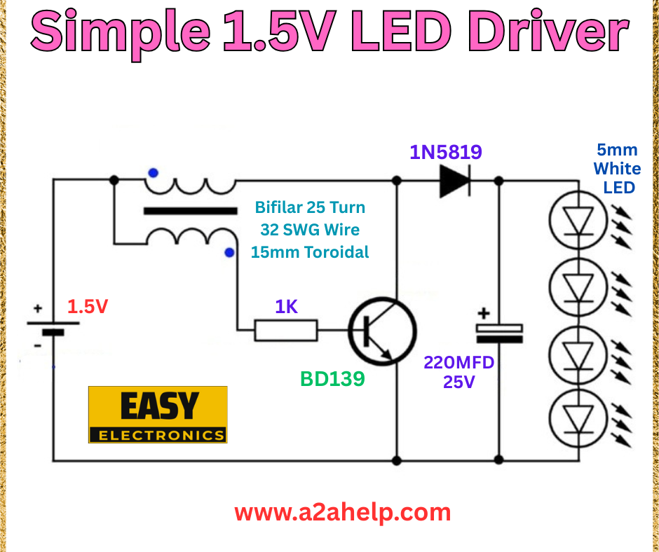
Looking to power LEDs with a low-voltage source like a 1.5V battery? A simple 1.5V LED driver circuit is the perfect DIY electronics project for hobbyists and beginners. This compact design uses minimal components to efficiently drive multiple LEDs, making it ideal for small lighting projects. In this step-by-step guide, we’ll explore how to build your own 1.5V LED driver using the provided circuit diagram. Let’s get started!
What Is a 1.5V LED Driver?
A 1.5V LED driver is an electronic circuit that boosts a 1.5V input (e.g., from a single AA battery) to a level sufficient to power white LEDs, which typically require around 3-3.5V. This circuit uses a transformer and transistor setup to step up the voltage, offering a practical solution for low-power LED applications.
Components You’ll Need
To construct this 1.5V LED driver, gather the following materials:
- 1.5V DC power supply (e.g., AA battery)
- BD139 NPN transistor
- 1N5819 Schottky diode
- 1kΩ resistor
- 220µF capacitor (25V)
- Bifilar wound transformer (25 turns, 32 SWG wire, 15mm toroidal core)
- 5mm white LEDs (x4)
- Connecting wires
- Soldering kit and breadboard (for prototyping)
Understanding the Circuit Diagram

- Bifilar Transformer: Steps up the 1.5V input using a 25-turn coil with 32 SWG wire on a 15mm toroidal core.
- BD139 Transistor: Acts as a switch to drive the transformer and regulate current.
- 1N5819 Diode: Provides rectification to convert AC to DC for the LEDs.
- 1kΩ Resistor: Limits the base current to the transistor.
- 220µF Capacitor: Smooths the output voltage for stable LED operation.
- LEDs: Four 5mm white LEDs connected in parallel, drawing power from the boosted voltage.
Step-by-Step Construction Guide
Step 1: Assemble the Transformer
- Wind 25 turns of 32 SWG wire bifilar-style on a 15mm toroidal core.
- Connect one end of each winding to the 1.5V supply and the other ends to the transistor collector.
Step 2: Set Up the Transistor Circuit
- Attach the 1kΩ resistor between the 1.5V supply and the BD139 base.
- Connect the emitter to ground and the collector to the transformer windings.
Step 3: Add the Diode and Capacitor
- Wire the 1N5819 diode with its anode to the transformer output and cathode to the positive LED terminal.
- Place the 220µF capacitor across the LED positive and ground to filter the output.
Step 4: Connect the LEDs
- Link the four 5mm white LEDs in parallel, with their anodes to the capacitor positive and cathodes to ground.
Step 5: Power and Test
- Connect the 1.5V battery to the circuit.
- If wired correctly, the LEDs should light up, indicating the circuit is functioning.
Benefits of a 1.5V LED Driver
- Energy Efficient: Operates on a single 1.5V battery.
- Compact Design: Ideal for small-scale lighting projects.
- Cost-Effective: Uses affordable, widely available components.
Troubleshooting Tips
- LEDs Not Lighting: Check the transformer windings and diode orientation.
- Dim Output: Ensure the capacitor value is correct and the battery is fresh.
- Overheating: Verify the transistor is handling the current load.
Why Choose This Project?
This 1.5V LED driver is perfect for electronics enthusiasts or anyone looking to create portable lighting solutions. With easily sourced parts, you can build it quickly, making it great for DIY lamps, emergency lights, or decorative displays. It’s a fantastic way to learn about voltage boosting while creating something useful.
Conclusion
Building a simple 1.5V LED driver circuit is a rewarding project that combines ease with practicality. By following this guide and using the provided circuit diagram, you can power LEDs efficiently with a low-voltage source. Visit www.a2ahelp.com for more exciting electronics projects and start your DIY journey today!
