Are you looking to create a stable and efficient power supply for your electronics projects? A regulated power supply using a MOSFET is an excellent choice for delivering consistent voltage from an unregulated DC source. This article provides a detailed, step-by-step guide to building a regulated power supply with the IRF5305 MOSFET, perfect for hobbyists and professionals alike. Let’s get started!
What is a Regulated Power Supply Using MOSFET?
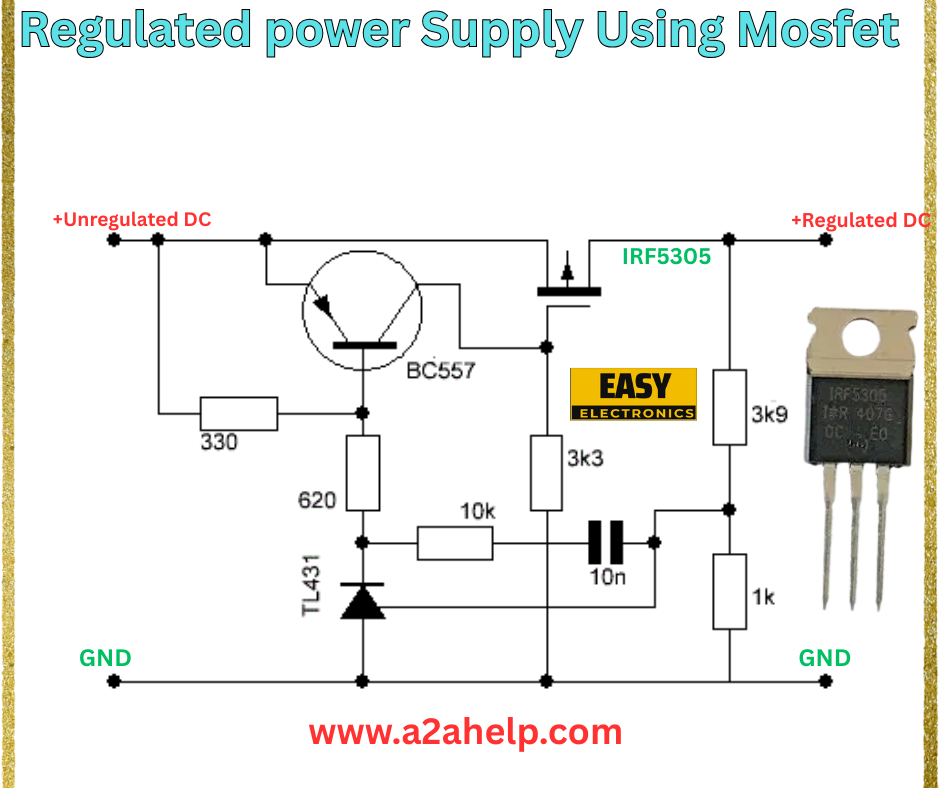
A regulated power supply maintains a constant output voltage despite variations in input voltage or load current. The circuit in the image uses a MOSFET (IRF5305) combined with a TL431 voltage reference and a BC557 transistor to regulate the output, making it ideal for applications requiring precise power delivery.
Components Required
To build this regulated power supply, gather the following components:
- IRF5305 MOSFET: Acts as the main switching and regulating element.
- BC557 Transistor: Provides amplification and control.
- TL431 Adjustable Voltage Reference: Ensures precise voltage regulation.
- Resistors: 330Ω, 620Ω, 3k3Ω, 10kΩ, 1kΩ.
- Capacitor: 10nF for stability.
- Unregulated DC Source: Input voltage to be regulated.
- PCB and Wires: For circuit assembly.
Circuit Diagram Analysis
The schematic is a well-designed linear regulator circuit. Here’s a breakdown:

- Input Stage: The unregulated DC input is applied to the circuit.
- Voltage Reference: The TL431, configured with a 620Ω and 10kΩ resistor network, sets the reference voltage.
- Control Stage: The BC557 transistor amplifies the error signal from the TL431, controlling the IRF5305 MOSFET.
- Output Stage: The IRF5305 regulates the voltage, with a 3k3Ω and 1kΩ resistor network stabilizing the output. A 330Ω resistor and 10nF capacitor enhance performance.
- Ground (GND): Common ground connection for the circuit.
Step-by-Step Assembly Guide
- Prepare the PCB: Design or etch a PCB based on the schematic for a tidy layout.
- Mount the MOSFET and Transistor: Solder the IRF5305 and BC557, ensuring proper heat dissipation for the MOSFET.
- Connect the TL431: Place the TL431 and connect the 620Ω and 10kΩ resistors to set the reference voltage.
- Add Resistors and Capacitor: Solder the 330Ω, 3k3Ω, 1kΩ resistors, and 10nF capacitor as per the diagram.
- Wire the Circuit: Connect the unregulated DC input and ground lines.
- Test the Circuit: Apply power and use a multimeter to verify the regulated output voltage. Adjust the resistor values if needed.
Safety Precautions
- Ensure the MOSFET is mounted with a heat sink to prevent overheating.
- Verify all connections to avoid short circuits.
- Test with a low load initially to confirm stability.
Applications
This regulated power supply is perfect for:
- Powering sensitive electronic devices.
- DIY audio amplifiers and LED drivers.
- Battery charging circuits.
Troubleshooting Tips
- No Output Voltage: Check the TL431 reference and transistor connections.
- Unstable Output: Ensure the 10nF capacitor is correctly placed and test resistor values.
- Overheating: Improve heat sinking or reduce input voltage.
Conclusion
Building a regulated power supply using a MOSFET is a valuable skill for any electronics enthusiast. This circuit offers reliability and precision for a variety of applications. For more electronics projects and schematics, visit www.a2ahelp.com. Start your project today and power your innovations with confidence!
