Are you looking for a safe and efficient way to detect live AC wires without direct contact? A non-contact AC tester is an essential tool for electricians, hobbyists, and DIY enthusiasts. This simple yet effective device uses a basic circuit to detect alternating current (AC) voltage, making it ideal for troubleshooting electrical systems. In this step-by-step guide, we’ll show you how to build your own non-contact AC tester using easily available components.
What is a Non-Contact AC Tester?
A non-contact AC tester detects the presence of AC voltage in wires or circuits without requiring physical contact. It works by sensing the electric field generated by live wires, lighting up an LED to indicate voltage. This project operates on a 6V power supply and is perfect for safely identifying live circuits in homes, offices, or workshops.
Key Components
- BC547 Transistors: NPN transistors used in a Darlington pair configuration for amplification.
- Resistors: 1MΩ, 100kΩ, and 220Ω for biasing and current limiting.
- LED (Red): Indicates the presence of AC voltage.
- Antenna: A small metal spring or wire to sense the electric field.
- Power Supply: 6V battery or adapter.
Step-by-Step Guide to Building a Non-Contact AC Tester

1. Gather Your Materials
Collect all required components and tools, including a soldering iron, PCB or perf board, wire cutters, and a 6V power source. Sourcing parts from reputable suppliers like Easy Electronics ensures reliability and performance.
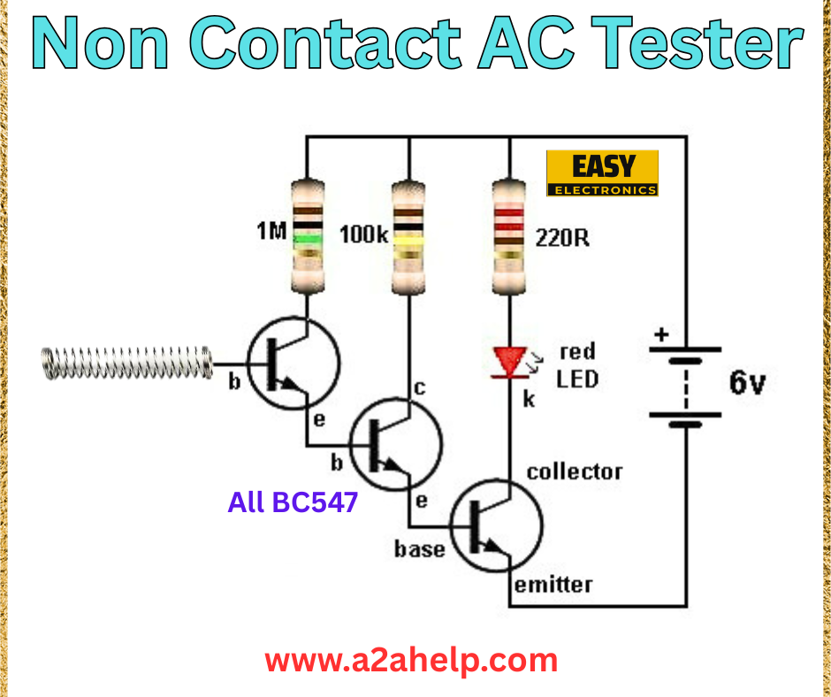
2. Assemble the Circuit
Follow the schematic diagram carefully:
- Attach the antenna (metal spring) to the base of the first BC547 transistor.
- Connect a 1MΩ resistor between the antenna and the base to limit input current.
- Link the emitter of the first BC547 to the base of the second BC547, forming a Darlington pair.
- Place a 100kΩ resistor between the base of the second transistor and ground for stability.
- Connect the collector of the second BC547 to the positive terminal of the LED via a 220Ω resistor.
- Attach the LED’s cathode to the negative terminal of the 6V power supply.
- Ensure the emitters of both transistors are grounded.
3. Test the Tester
Before use, test the circuit by bringing the antenna near a known live AC wire. The LED should light up if voltage is detected. Adjust the antenna sensitivity by tweaking the 1MΩ resistor if needed.
4. Enclose the Circuit
Place the assembled circuit in a non-conductive plastic casing with the antenna protruding for sensing. Add a switch to control power and ensure all connections are insulated.
5. Use Safely
Hold the tester near wires or outlets to detect AC voltage. The LED will glow in the presence of live current, allowing you to identify active circuits without risk.
Benefits of a DIY Non-Contact AC Tester
- Safety: Eliminates the need for direct contact with live wires.
- Portability: Compact and easy to carry for on-the-go use.
- Cost-Effective: Uses affordable, widely available components.
- Versatility: Ideal for home repairs, electrical inspections, and DIY projects.
Troubleshooting Common Issues
- LED Not Lighting: Check the battery, ensure proper grounding, and verify antenna placement.
- False Positives: Adjust the 1MΩ resistor to reduce sensitivity.
- Weak Signal: Confirm the Darlington pair connection and replace faulty transistors.
Safety Tips
- Always test with a known live wire first to verify functionality.
- Avoid using near high-voltage lines without proper training.
- Keep the device away from water to prevent short circuits.
Conclusion
Building a non-contact AC tester is a practical and educational project that enhances your electronics skills while providing a valuable tool for electrical work. By following this guide and using the schematic from a2ahelp.com, you can create a reliable tester for your needs. Explore more DIY electronics projects on our site and subscribe for the latest updates!
