Are you looking for a reliable and cost-effective way to ensure light during power outages? Building a DIY emergency light circuit is a practical solution for every home or workshop. This article provides a detailed guide on constructing an emergency light using a simple schematic, perfect for electronics enthusiasts. Let’s dive into the process and illuminate your space!
What is an Emergency Light Circuit?
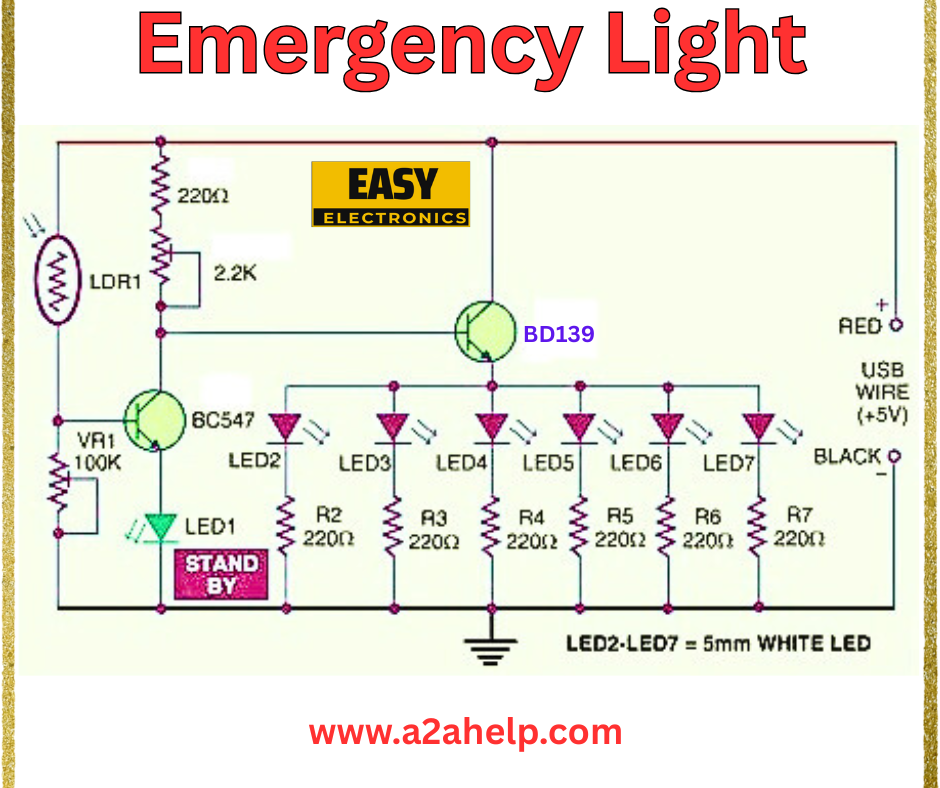
An emergency light circuit automatically activates during power failures, providing illumination using a backup power source. The circuit in the image uses a light-dependent resistor (LDR) to detect darkness and a transistor-based design to power LED lights, making it an efficient and affordable option.
Components Required
To build this emergency light, you’ll need the following components:
- LDR1 (Light Dependent Resistor): Detects ambient light levels.
- BC547 Transistor: Acts as a switch to control the circuit.
- BD139 Transistor: Drives the LED array.
- LEDs (LED2-LED7): 5mm white LEDs for illumination.
- LED1: Standby indicator LED.
- Resistors: 220Ω (R2-R7), 2kΩ, 10kΩ (VR1).
- USB Wire: Provides 5V power input (red for positive, black for ground).
- PCB and Wires: For assembling the circuit.
Circuit Diagram Analysis
The schematic is designed for simplicity and effectiveness. Here’s a breakdown:

- Light Sensing: LDR1, paired with a 2kΩ resistor and 10kΩ variable resistor (VR1), forms a voltage divider. When ambient light decreases, the LDR resistance increases, triggering the circuit.
- Switching Stage: The BC547 transistor activates based on the LDR input, turning on the BD139 transistor.
- LED Array: BD139 drives six 5mm white LEDs (LED2-LED7) in parallel, each with a 220Ω current-limiting resistor (R2-R7).
- Power Input: A USB wire supplies 5V, with LED1 indicating standby mode.
Step-by-Step Assembly Guide
- Prepare the PCB: Etch or design a PCB based on the schematic for a clean layout.
- Mount the Transistors: Solder the BC547 and BD139 transistors, ensuring correct pin orientation.
- Connect the LDR and Resistors: Attach LDR1, VR1, and the 2kΩ resistor to form the light-sensing network.
- Install the LEDs: Place LED2-LED7 in parallel with their respective 220Ω resistors. Add LED1 for standby indication.
- Wire the Power: Connect the USB wire (red for 5V, black for ground) to the circuit.
- Test the Circuit: Power it via USB and adjust VR1 to set the light threshold. The LEDs should light up in darkness.
Safety Precautions
- Handle LEDs carefully to avoid damaging them with reverse voltage.
- Ensure proper heat dissipation for the transistors during prolonged use.
- Use insulated wires to prevent short circuits.
Applications
This emergency light is ideal for:
- Home power backup during outages.
- Camping or outdoor activities.
- Small workshop lighting solutions.
Troubleshooting Tips
- LEDs Not Lighting: Check the USB power supply and transistor connections.
- No Response to Darkness: Adjust VR1 or test the LDR for functionality.
- Dim LEDs: Verify resistor values and ensure adequate current from the USB source.
Conclusion
Creating a DIY emergency light circuit is a rewarding project that ensures safety and convenience. With basic components and this guide, you can build a reliable light source for any situation. For more electronics projects and schematics, visit www.a2ahelp.com. Start building today and stay prepared!
