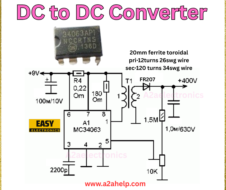
Are you looking to step up your electronics game? A DC to DC converter is an essential circuit for hobbyists and professionals alike, allowing you to efficiently convert one DC voltage level to another. In this article, we’ll walk you through a practical DIY DC to DC converter circuit using the MC34063A IC, complete with a detailed schematic and component list. Whether you’re a beginner or an experienced engineer, this guide will help you understand and build your converter. Let’s dive in!
What is a DC to DC Converter?
A DC to DC converter is an electronic circuit that converts a source of direct current (DC) from one voltage level to another. This is particularly useful in applications where a device requires a different voltage than what’s supplied by the power source. For instance, converting +9V to +400V, as shown in the schematic below, is a common requirement in high-voltage projects.
Understanding the Circuit Diagram
The image above provides a clear schematic for a DC to DC converter using the MC34063A, a versatile switching regulator IC. This circuit steps up +9V to +400V, making it ideal for applications like tube amplifiers or high-voltage displays. Here’s a breakdown of the components and their roles:
- MC34063A IC (U1): The heart of the circuit, this IC handles the switching regulation to step up the voltage.
- T1 (Transformer): A 20mm ferrite toroidal transformer with a primary winding of 12 turns (26swg wire) and a secondary winding of 120 turns (34swg wire).
- D1 (FR207 Diode): Ensures current flows in the correct direction, protecting the circuit.
- R4 (0.22Ω Resistor): Limits current to the IC.
- R5 (180Ω Resistor): Works with the capacitor to set the oscillator frequency.
- C1 (100µF/10V Capacitor): Smooths the input voltage.
- C2 (1.5µF/630V Capacitor): Filters the output voltage.
- L1 (220µH Inductor): Stores energy for the step-up process.
- R6 (10kΩ Resistor): Provides bias for the feedback loop.
- C3 (1µF/630V Capacitor): Additional output filtering.

Step-by-Step Guide to Building the DC to DC Converter
Materials Needed
- MC34063A IC
- 20mm ferrite toroidal core
- 26swg and 34swg enameled copper wire
- FR207 diode
- Resistors: 0.22Ω, 180Ω, 10kΩ
- Capacitors: 100µF/10V, 1.5µF/630V, 1µF/630V
- 220µH inductor
- Soldering iron, solder, and flux
- Multimeter for testing
- Breadboard or PCB
Assembly Instructions
- Prepare the Transformer: Wind 12 turns of 26 swg wire for the primary and 120 turns of 34 swg wire for the secondary on a 20 mm ferrite toroidal core. Ensure the windings are properly insulated and securely fastened.
- Mount the IC: Place the MC34063A IC on your breadboard or PCB, aligning the pins as per the schematic (pins 1-8).
- Connect the Resistors and Capacitors: Solder R4 (0.22Ω) and R5 (180Ω) to the IC pins as shown. Attach C1 (100µF/10V) to the input and C2 (1.5µF/630V) to the output.
- Add the Diode and Inductor: Connect the FR207 diode (D1) and the 220µH inductor (L1) according to the circuit diagram.
- Wire the Transformer: Connect the primary and secondary windings of T1 to the respective points in the circuit.
- Final Connections: Add R6 (10kΩ) and C3 (1µF/630V) to complete the feedback and filtering stages.
- Power Up and Test: Apply +9V to the input and use a multimeter to measure the output voltage. Adjust components if the output deviates from +400V.
Safety Tips
- Always double-check your connections to avoid short circuits.
- Use a multimeter to verify voltages before powering the circuit.
- Handle high-voltage outputs (e.g., +400V) with care to prevent electric shock.
Applications of DC to DC Converters
DC to DC converters are widely used in:
- Portable Electronics: To power devices from a single battery source.
- Automotive Systems: For converting 12V to 5V or other levels.
- Renewable Energy: Solar panels to match load requirements.
- High-Voltage Projects: Like the +400V output in this circuit for specialized equipment.
Troubleshooting Common Issues
- No Output Voltage: Check the IC and transformer connections. Ensure the input voltage is stable.
- Unstable Output: Verify capacitor values and replace if faulty.
- Overheating: Reduce load or check for short circuits.
Why Choose the MC34063A?
The MC34063A is a popular choice due to its simplicity, cost-effectiveness, and ability to handle a wide range of input voltages. It’s perfect for DIY projects and small-scale applications, making it a favorite among electronics enthusiasts.
Conclusion
Building a DC to DC converter with the MC34063A is a rewarding project that enhances your understanding of power electronics. By following this guide, you can create a reliable +9V to +400V converter for your next project. For more electronics tutorials and schematics, visit www.a2ahelp.com. Have questions or need assistance? Feel free to leave a comment below!
