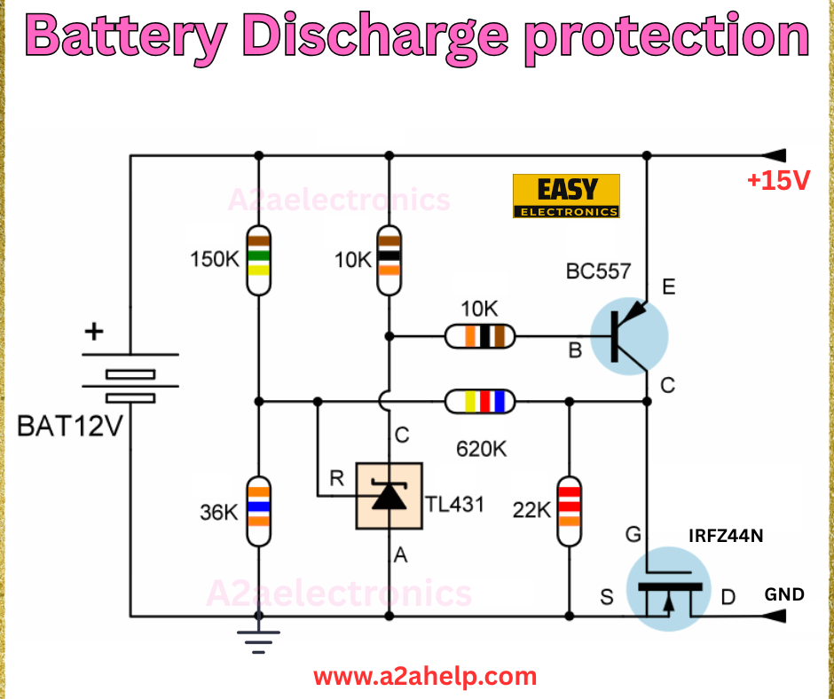
Protecting your batteries from over-discharge is crucial to extend their lifespan and ensure safety in your electronic projects. A battery discharge protection circuit can prevent damage by cutting off the load when the battery voltage drops too low. In this guide, we’ll explore a simple yet effective circuit using the TL431 voltage regulator and an IRFZ44N MOSFET, designed to protect a 12V battery. Whether you’re a DIY enthusiast or a professional engineer, this tutorial will help you build and understand this essential circuit. Let’s get started!
What is Battery Discharge Protection?
Battery discharge protection is a mechanism that monitors the voltage of a battery and disconnects the load when it falls below a safe threshold. This prevents deep discharge, which can lead to irreversible damage, reduced capacity, or even safety hazards like leakage or explosion. The circuit below uses a 12V battery input and provides a +15V output, with protection triggered by a voltage comparator.
Analyzing the Circuit Diagram
The schematic above details a battery discharge protection circuit with the following components and their roles:
- TL431 (U1): A programmable shunt regulator that acts as a voltage comparator to monitor battery levels.
- IRFZ44N MOSFET (Q1): A power MOSFET that switches the load on or off based on the TL431’s output.
- BC557 Transistor (Q2): Amplifies the TL431 signal to drive the MOSFET.
- R1 (150kΩ): Sets the reference voltage for the TL431.
- R2 (10kΩ): Forms a voltage divider with R1 to adjust the threshold.
- R3 (10kΩ): Provides bias to the BC557 base.
- R4 (36kΩ): Part of the voltage divider network.
- R5 (620kΩ): Fine-tunes the reference voltage.
- R6 (22kΩ): Limits current to the MOSFET gate.
- BAT12V: The 12V battery to be protected.

Step-by-Step Guide to Building the Circuit
Materials Needed
- TL431 voltage regulator
- IRFZ44N MOSFET
- BC557 PNP transistor
- Resistors: 150kΩ, 10kΩ (2), 36kΩ, 620kΩ, 22kΩ
- 12V battery
- Breadboard or PCB
- Soldering iron, solder, and flux
- Multimeter for testing
- Connecting wires
Assembly Instructions
- Prepare the TL431: Place the TL431 on your breadboard or PCB. Connect the reference pin (R) to ground via R1 (150kΩ) and R4 (36kΩ) in series. Link the cathode (C) to the anode (A) through R5 (620kΩ).
- Set Up the Voltage Divider: Connect R2 (10kΩ) between the battery positive terminal and the TL431 reference pin, and R3 (10kΩ) from the reference pin to the BC557 base.
- Add the BC557 Transistor: Connect the emitter (E) of the BC557 to the battery positive terminal, the base (B) to the TL431 reference pin via R3, and the collector (C) to the IRFZ44N gate.
- Install the MOSFET: Attach the gate (G) of the IRFZ44N to the BC557 collector via R6 (22kΩ). Connect the source (S) to ground and the drain (D) to the load (output +15V).
- Connect the Battery: Wire the 12V battery positive to the circuit input and the negative to ground.
- Test the Circuit: Apply 12V and use a multimeter to monitor the output. The circuit should cut off the load when the battery voltage drops below the set threshold (around 10.5V-11V).
Safety Tips
- Handle the battery with care to avoid short circuits.
- Use a multimeter to verify voltage levels before and after testing.
- Ensure proper grounding to prevent erratic behavior.
How It Works
The TL431 monitors the battery voltage through the voltage divider (R1 and R4). When the voltage drops below the preset threshold, the TL431 output changes, triggering the BC557 to turn off the IRFZ44N MOSFET. This disconnects the load, protecting the battery. The circuit resumes operation once the battery is recharged.
Applications of Battery Discharge Protection
- Portable Devices: Safeguard batteries in solar chargers or power banks.
- Electric Vehicles: Prevent over-discharge in EV battery packs.
- DIY Projects: Protect homemade power supplies or robotics systems.
Troubleshooting Common Issues
- No Output: Check the TL431 and MOSFET connections. Ensure the battery voltage is above the threshold.
- False Triggering: Adjust R1 and R4 values to fine-tune the voltage threshold.
- Overheating: Verify the MOSFET is not overloaded and add a heat sink if needed.
Why Use TL431 and IRFZ44N?
The TL431 offers precise voltage monitoring, while the IRFZ44N provides efficient power switching. This combination ensures reliable protection and minimal power loss, making it ideal for battery-powered applications.
Conclusion
Building a battery discharge protection circuit with the TL431 and IRFZ44N is a practical way to safeguard your 12V battery projects. Follow this guide to assemble your circuit and enjoy peace of mind with extended battery life. For more electronics tutorials, visit www.a2ahelp.com. Have questions? Leave a comment below!
