Are you an electronics enthusiast looking to amplify your audio experience? Building your 60Watt amplifier circuit can be a rewarding project that enhances your understanding of electronics while delivering impressive sound quality. In this comprehensive guide, we’ll walk you through the process of constructing a 60Watt amplifier using a detailed circuit diagram. Whether you’re a hobbyist or a professional, this step-by-step tutorial will guide you in creating a powerful amplifier for your audio projects.
Understanding the 60Watt Amplifier Circuit
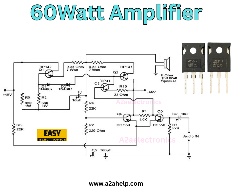
The 60Watt amplifier circuit is designed to deliver robust audio output, making it ideal for home audio systems or small PA setups. This circuit utilizes high-quality components, including TIP142, TIP147, and BC558 transistors, along with precise resistor and capacitor values, to ensure optimal performance. The diagram, credited to www.a2ahelp.com, provides a clear layout for assembling the amplifier, including connections for a 150 Ohm speaker and a -45V power supply.
Key Components of the 60Watt Amplifier
- Transistors: TIP142, TIP147, TIP41, and BC558 for amplification and switching.
- Resistors: 0.33 Ohm (7W), 22K, 33K, 220 Ohm, 1.5K, 27K for current and voltage control.
- Capacitors: 10µF and 100µF for coupling and filtering.
- Diodes: 1N4007 for protection.
- Speaker: 150 Ohm, 150W for output.
These components work together to amplify the audio input signal, providing a clean and powerful 60W output.

Step-by-Step Guide to Building the 60Watt Amplifier
Step 1: Gather Your Materials
Before starting, ensure you have all the necessary components and tools:
- Soldering iron and solder
- Multimeter for testing
- Breadboard or PCB
- Power supply (-45V)
- Audio input source
- Safety gear (gloves, goggles)
Step 2: Study the Circuit Diagram
Refer to the provided image from A2aelectronics. The diagram highlights the placement of each component, including the transistor configuration and resistor values. Take note of the positive and negative terminals to avoid reverse polarity issues.
Step 3: Assemble the Circuit
- Start with the Transistors: Place TIP142 and TIP147 on the heat sink for thermal management. Connect TIP41 and BC558 according to the diagram.
- Add Resistors and Capacitors: Solder the 0.33 Ohm resistors (7W) and 10µF capacitors in their designated spots. Ensure the 100µF capacitors are correctly polarized.
- Incorporate Diodes: Connect the 1N4007 diodes for protection against voltage spikes.
- Wire the Speaker: Attach the 150 Ohm, 150W speaker to the output terminals.
- Connect the Power Supply: Link the -45V supply to the circuit, double-checking all connections.
Step 4: Test the Amplifier
- Power on the circuit with a low audio input.
- Use a multimeter to check for proper voltage across key points.
- Gradually increase the input and listen for a clear sound from the speaker.
- Adjust resistor values if needed to fine-tune performance.
Step 5: Final Touches
Once tested, secure all connections with insulating tape or heat shrink tubing. Enclose the circuit in a protective casing to prevent short circuits and ensure safety.
Tips for Success
- Heat Management: Transistors like TIP142 and TIP147 generate heat; always use a heat sink.
- Safety First: Work in a well-ventilated area and avoid touching live circuits.
- Troubleshooting: If the output is distorted, check for loose connections or incorrect component placement.
Benefits of Building Your 60Watt Amplifier
Creating your amplifier allows for customization, cost savings, and a deeper understanding of electronics. This 60Watt design is perfect for driving medium-sized speakers, making it a versatile addition to your audio setup.
Conclusion
Building a 60Watt amplifier is a fantastic project for electronics enthusiasts. By following this guide and using the circuit diagram from A2electronics, you can achieve a high-quality audio amplifier tailored to your needs. For more electronics projects and detailed schematics, visit www.a2ahelp.com. Start your build today and enjoy the power of your homemade 60Watt amplifier!
