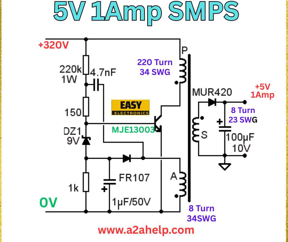
Are you an electronics enthusiast looking to create a compact and efficient 5V 1A Switch-Mode Power Supply (SMPS) for your projects? Building your own SMPS can be a rewarding experience, offering a reliable power source for various devices. In this detailed guide, we’ll walk you through the process of constructing a 5V 1A SMPS using a simple circuit diagram. Perfect for beginners and experts alike, this tutorial will help you get started. Let’s explore the steps!
Understanding the 5V 1A SMPS Circuit
A Switch-Mode Power Supply (SMPS) is an efficient alternative to traditional linear power supplies, converting high voltage AC to low voltage DC with minimal power loss. The circuit diagram for a 5V 1A SMPS includes key components like the MJE13003 transistor, MUR420 diode, and a custom transformer. Let’s break down the design and its functionality.
Components Required
- 220kΩ 1W Resistor: Limits current in the startup circuit.
- 4.7nF Capacitor: Filters high-frequency noise.
- 9V Zener Diode (DZ1): Regulates voltage for the transistor base.
- 1kΩ Resistor: Provides base current to the transistor.
- MJE13003 Transistor: Acts as the switching element.
- FR107 Diode: Rectifies the feedback voltage.
- 1µF/50V Capacitor: Smooths the DC output.
- Transformer: Custom wound with 220 turns (34 SWG) primary and 8 turns (34 SWG) secondary.
- MUR420 Diode: High-speed rectifier for the secondary.
- 100µF/10V Capacitor: Filters the 5V output.
- Connecting Wires and Breadboard: For circuit assembly.
Step-by-Step Guide to Building the 5V 1A SMPS

Step 1: Gather Your Tools and Components
Collect all the listed components and tools, including a soldering iron, multimeter, and insulated wires. Ensure you have a steady hand and a well-ventilated workspace.
Step 2: Set Up the Input Circuit
Connect the 220kΩ 1W resistor and 4.7nF capacitor in series to the +320V input. This forms the startup circuit, feeding initial voltage to the transistor. Ground the other end of the capacitor.
Step 3: Install the Zener Diode and Resistor
Connect the 9V Zener diode (DZ1) and 1kΩ resistor in series from the junction of the resistor-capacitor pair to the base of the MJE13003 transistor. This regulates the base voltage.
Step 4: Add the MJE13003 Transistor
Place the MJE13003 transistor in the circuit. Connect the emitter to ground, the collector to the primary winding of the transformer, and the base to the Zener diode circuit. This transistor switches the current through the transformer.
Step 5: Wind the Transformer
Create a custom transformer with a ferrite core EE19. Wind 220 turns of 34 SWG wire for the primary (P) ,8 turn 34 SWG for feedback and 8 turns of 23 SWG wire for the secondary (S). Ensure proper insulation between windings.
Step 6: Connect the Rectification Circuit
Attach the MUR420 diode to the secondary winding, with the anode connected to the transformer output. Connect the cathode to the positive terminal of the 100µF/10V capacitor. This rectifies and filters the 5V 1A output.
Step 7: Add Output Filtering
Place the MUR420 diode and 1µF/50V capacitor across the transformer secondary to the ground. This further smooths the output voltage.
Step 8: Test the Circuit
Apply +320V to the input and use a multimeter to measure the output across the 100µF capacitor. It should read approximately 5V with a 1A load. Ensure no overheating or short circuits occur.
Safety Tips for Building Your SMPS
- Wear insulated gloves and safety goggles.
- Verify all connections to prevent short circuits.
- Use a multimeter to check voltage and current.
- Handle the transformer windings carefully to avoid damage.
Benefits of a DIY 5V 1A SMPS
- Energy Efficient: Reduces power loss compared to linear supplies.
- Compact Design: Ideal for space-constrained projects.
- Cost-Effective: Save money by building your own.
Troubleshooting Common Issues
- No Output Voltage: Check the transformer windings and transistor.
- Overheating: Ensure proper heat sinking for the transistor.
- Unstable Output: Verify capacitor values and diode connections.
Conclusion
Building a 5V 1A SMPS is a fantastic project for electronics hobbyists. With this guide, you can create a reliable power supply for your devices using affordable components. For more electronics projects and tips, visit www.a2ahelp.com. Start your DIY journey today and power up your creations!
