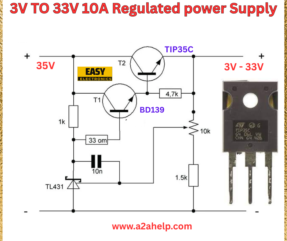
Are you looking to create a reliable and adjustable power supply for your electronics projects? A 3V to 33V 10A regulated power supply is an excellent solution for powering a wide range of devices, from small circuits to high-current applications. In this comprehensive guide, we’ll walk you through the process of building your own regulated power supply using a simple yet effective circuit design. Whether you’re a hobbyist or a professional electronics engineer, this step-by-step tutorial will help you achieve excellent results.
Understanding the 3V to 33V 10A Regulated Power Supply
A regulated power supply ensures a stable output voltage and current, making it ideal for sensitive electronic components. This particular design allows you to adjust the output voltage between 3V and 33V while delivering up to 10A of current. The circuit uses common components like transistors, resistors, and an integrated circuit to achieve precise regulation and high efficiency.
Key Components
- TIP35C Transistor (T2): A high-power NPN transistor for current amplification.
- BD139 Transistor (T1): Used as a driver transistor to control the power stage.
- TL431 Voltage Regulator IC: Provides precise voltage regulation.
- Resistors: 1kΩ, 33Ω, 4.7kΩ, 10kΩ, and 1.5kΩ for biasing and feedback.
- Capacitor: 10nF for stabilizing the circuit.
- Input Voltage: 35V DC supply.
- Output Range: Adjustable from 3V to 33V at 10A.

Step-by-Step Guide to Building the Circuit
1. Gather Your Materials
Before starting, ensure you have all the necessary components and tools, including a soldering iron, PCB or breadboard, multimeter, and a 35V DC power source. High-quality components from trusted suppliers like Easy Electronics will ensure the longevity and performance of your power supply.
2. Assemble the Circuit
Follow the schematic diagram carefully:
- Connect the 35V DC input to the collector of the TIP35C transistor (T2).
- Attach a 1kΩ resistor between the base of T2 and the collector of the BD139 transistor (T1).
- Link a 33Ω resistor and a 10nF capacitor in parallel between the emitter of T2 and ground for stability.
- Connect the TL431 IC, with its reference pin tied to a 1.5kΩ resistor and a 10kΩ potentiometer for voltage adjustment.
- Use a 4.7kΩ resistor between the base of T1 and the cathode of the TL431 to form the feedback loop.
- The output voltage (3V to 33V) is taken from the emitter of T2.
3. Test the Circuit
Before applying full load, test the circuit with a multimeter to verify the output voltage. Adjust the potentiometer to set the desired voltage between 3V and 33V. Ensure the current does not exceed 10A by monitoring with an ammeter or a current-limiting setup.
4. Heat Management
Since this circuit handles up to 10A, the TIP35C transistor will generate significant heat. Attach a suitable heat sink to prevent overheating and ensure reliable operation.
5. Final Adjustments
Fine-tune the output voltage and test the power supply with your target load. Ensure all connections are secure and insulated to avoid short circuits.
Benefits of a 3V to 33V 10A Regulated Power Supply
- Versatility: Suitable for a wide range of applications, from DIY projects to industrial uses.
- Stability: The TL431 ensures consistent output voltage despite load changes.
- High Current Capacity: Delivers up to 10A, making it ideal for power-hungry devices.
- Cost-Effective: Uses affordable, readily available components.
Troubleshooting Common Issues
- No Output Voltage: Check the input supply and ensure all connections are intact.
- Overheating: Verify the heat sink is properly installed and the load is within 10A.
- Unstable Voltage: Adjust the potentiometer or check the TL431 and surrounding components for faults.
Safety Tips
- Always work with the power supply disconnected from the input source during assembly.
- Use insulated tools and wear protective gear to avoid electrical shocks.
- Double-check polarity to prevent damage to components.
Conclusion
Building a 3V to 33V 10A regulated power supply is a rewarding project that enhances your electronics skills while providing a versatile power source for your creations. By following this guide and using the schematic from a2ahelp.com, you can create a reliable and efficient power supply tailored to your needs. For more electronics projects and tutorials, explore our website and subscribe for the latest updates!
