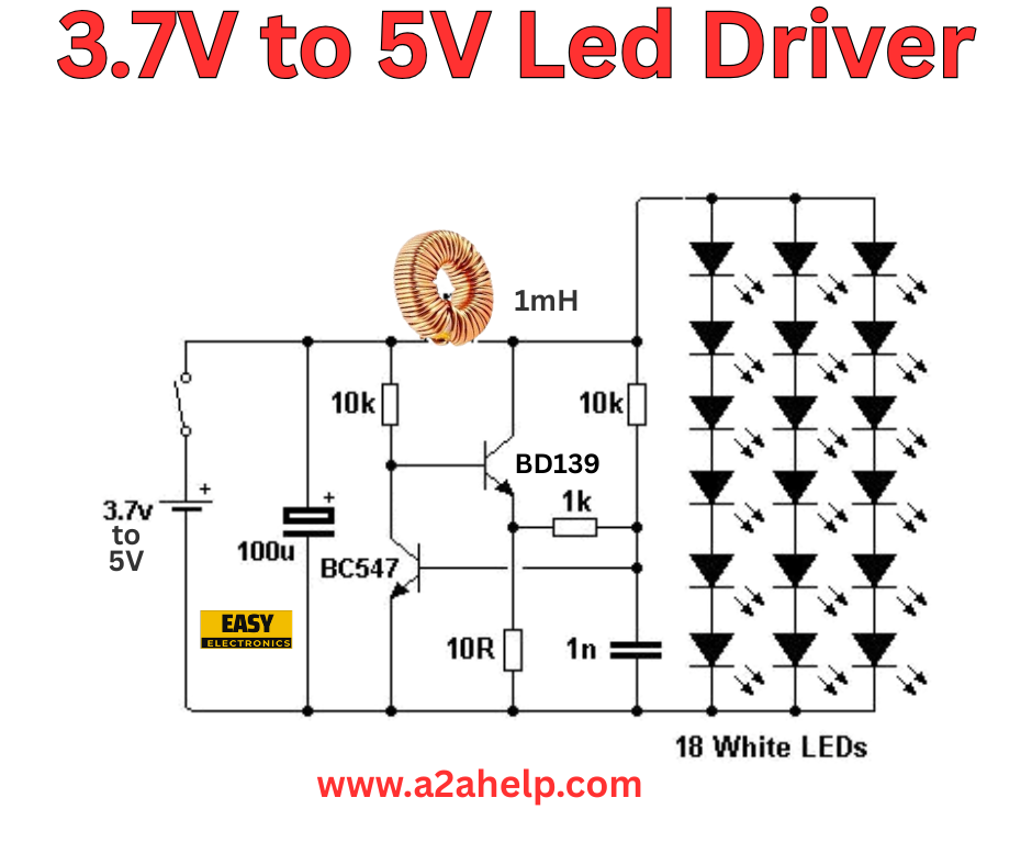
If you’re an electronics enthusiast or a DIY hobbyist looking to power LED lights efficiently, understanding how to create a 3.7V to 5V LED driver circuit is a valuable skill. This article provides a detailed, step-by-step guide to building a reliable LED driver circuit using the schematic shown above. Whether you’re working on a small project or upgrading your lighting setup, this tutorial will help you get started. Let’s dive into the components, assembly process, and tips to ensure your circuit works flawlessly.
What Is a 3.7V to 5V LED Driver Circuit?
A 3.7V to 5V LED driver circuit is designed to step up a 3.7V input voltage (commonly from a single lithium-ion battery) to 5V, which is suitable for driving multiple LEDs. This circuit is ideal for powering 18 white LEDs, as depicted in the schematic, making it perfect for applications like portable lighting, DIY lamps, or decorative displays.
Components Required
To build this LED driver circuit, you’ll need the following components:
- Inductor (1mH): Acts as an energy storage element in the boost converter.
- Transistor (BD139): A medium-power NPN transistor for switching.
- NPN Transistor (BC547): Used for controlling the circuit’s operation.
- Resistors: 10kΩ, 1kΩ, and 10Ω for current limiting and biasing.
- Capacitor (100µF): Stabilizes the output voltage.
- Capacitor (1nF): Filters high-frequency noise.
- 18 White LEDs: The load for the circuit.
- Power Source: 3.7V to 5V input (e.g., a lithium-ion battery).
- Breadboard and Connecting Wires: For prototyping and assembly.

Circuit Diagram Analysis
The provided schematic is a boost converter topology, which increases the input voltage from 3.7V to a level sufficient to power 18 white LEDs in series or parallel. Here’s a breakdown of the circuit:
- The 1mH inductor stores energy from the 3.7V source when the BD139 transistor switches on.
- The BC547 transistor acts as a switch controller, driven by the 10kΩ and 1kΩ resistors.
- The 100µF capacitor smooths the output voltage to ensure stable LED operation.
- The 1nF capacitor and 10Ω resistor form a snubber network to suppress voltage spikes.
- The 18 white LEDs are connected in a configuration (likely a series-parallel mix) to distribute the 5V output effectively.
Step-by-Step Assembly Guide
- Prepare the Breadboard: Set up your breadboard and ensure all connections are clean.
- Connect the Power Source: Attach the 3.7V input to the circuit, with the positive terminal linked to the inductor and the negative to ground.
- Install the Inductor: Place the 1mH inductor and connect it to the BD139 transistor’s collector.
- Add the Transistors: Mount the BD139 and BC547 transistors, connecting the base of BC547 to the 10kΩ resistor and the emitter to ground.
- Insert Resistors and Capacitors: Place the 1kΩ and 10Ω resistors as shown, along with the 100µF and 1nF capacitors for stabilization.
- Connect the LEDs: Arrange the 18 white LEDs in your desired configuration (consult the schematic for exact placement) and connect them to the output.
- Test the Circuit: Power on the circuit and use a multimeter to verify the output voltage is around 5V. Adjust resistor values if needed.
- Secure and Insulate: Once functional, secure all components and insulate exposed connections to prevent shorts.
How It Works
This circuit operates as a simple boost converter. When the BD139 transistor turns on, the inductor charges. When it turns off, the stored energy in the inductor is released, stepping up the voltage to 5V. The BC547 transistor and resistors regulate the switching, ensuring a stable output for the LEDs. The capacitors filter out noise and stabilize the voltage, protecting the LEDs from fluctuations.
Tips for Success
- Check Component Ratings: Ensure all transistors and capacitors can handle the current and voltage levels.
- Heat Management: Monitor the transistors for overheating and add a heatsink if necessary.
- LED Configuration: Verify the forward voltage of your LEDs (typically 3V for white LEDs) to avoid overloading the circuit.
- Safety First: Always disconnect power before making adjustments.
Applications of the 3.7V to 5V LED Driver
This LED driver circuit is versatile and can be used in:
- Portable Lighting: Power small LED lamps with a single battery.
- DIY Projects: Enhance hobbyist electronics with bright, efficient lighting.
- Emergency Lights: Create backup lighting solutions for power outages.
Troubleshooting Common Issues
- No Output Voltage: Check for loose connections or a faulty transistor.
- LEDs Not Lighting: Ensure correct polarity and sufficient voltage.
- Overheating: Reduce the load or improve ventilation.
Conclusion
Building a 3.7V to 5V LED driver circuit is a rewarding project for electronics enthusiasts. With the right components and careful assembly, you can power 18 white LEDs efficiently using a 3.7V source. This guide provides everything you need to get started, from component selection to troubleshooting. For more electronics projects and tutorials, visit www.a2ahelp.com. Happy building!
