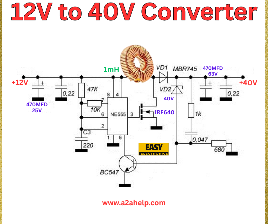
Are you looking to step up your voltage from 12V to 40V for your next electronics project? A 12V to 40V DC-DC converter is a fantastic solution for powering devices that require higher voltage levels. In this comprehensive guide, we’ll walk you through the design and assembly of a 12V to 40V converter circuit using a simple yet effective schematic. Whether you’re an electronics hobbyist or a professional engineer, this article will provide you with all the details you need to get started.
Understanding the 12V to 40V Converter
A DC-DC converter is an electronic circuit that converts a source of direct current (DC) from one voltage level to another. The circuit shown in the image is a boost converter, which steps up the input voltage (12V) to a higher output voltage (40V). This type of converter is widely used in applications like LED drivers, battery chargers, and portable devices.
Components Required
To build this 12V to 40V converter, you’ll need the following components:
- NE555 Timer IC: Acts as the oscillator to generate the switching frequency.
- IRF640 MOSFET: Serves as the switching element in the boost converter.
- BC547 Transistor: Used for driving the MOSFET.
- 1mH Inductor: Stores energy and releases it to step up the voltage.
- MBR745 Diode: Provides a path for the inductor current and rectifies the output.
- Capacitors: 470µF/25V and 470µF/63V for input and output filtering.
- Resistors: 0.22Ω, 47kΩ, 10kΩ, 1kΩ, 220Ω, 0.047Ω, and 680Ω for current limiting and biasing.
- Miscellaneous: PCB, connecting wires, and a power supply.
Circuit Diagram Analysis

The schematic provided features a classic boost converter topology. Here’s a breakdown of the circuit:
- Input Stage: The 12V DC input is filtered by a 470µF/25V capacitor to reduce noise.
- Oscillator Section: The NE555 timer, configured in astable mode, generates a square wave. Resistors (47kΩ, 10kΩ, and 220Ω) and capacitor C3 set the frequency.
- Switching Stage: The IRF640 MOSFET, driven by the BC547 transistor, switches the 1mH inductor on and off, creating the voltage boost.
- Output Stage: The MBR745 diode rectifies the induced voltage, and a 470µF/63V capacitor smooths the 40V output. Resistors (0.22Ω, 1kΩ, 0.047Ω, and 680Ω) help regulate the current.
Step-by-Step Assembly Guide
- Prepare the PCB: Etch or design a PCB based on the schematic. Ensure proper spacing for heat dissipation.
- Mount the IC and Transistor: Place the NE555 IC and BC547 transistor on the board, soldering them securely.
- Add the MOSFET and Diode: Solder the IRF640 MOSFET and MBR745 diode, ensuring correct polarity.
- Install the Inductor and Capacitors: Connect the 1mH inductor and the input/output capacitors as per the diagram.
- Connect Resistors: Solder the resistors in their designated positions to complete the biasing and current-limiting network.
- Wiring and Testing: Connect the 12V power supply and use a multimeter to check the output voltage. Adjust the resistor values if needed to fine-tune the 40V output.
Safety Precautions
- Always work with proper insulation and grounding to avoid electrical shocks.
- Ensure the components are rated for the voltages and currents they will handle.
- Test the circuit with a low load initially to verify functionality.
Applications of a 12V to 40V Converter
This converter is ideal for:
- Powering high-voltage LEDs.
- Charging 36V battery packs.
- Driving stepper motors or other high-voltage electronics.
Troubleshooting Tips
- No Output Voltage: Check the NE555 oscillator frequency and MOSFET switching.
- Overheating: Ensure the MOSFET and inductor are adequately cooled.
- Unstable Voltage: Verify capacitor values and connections.
Conclusion
Building a 12V to 40V DC-DC converter is a rewarding project that enhances your understanding of power electronics. With the right components and careful assembly, you can create a reliable voltage booster for various applications. For more detailed schematics and electronics projects, visit www.a2ahelp.com. Start your project today and power up your innovations!
