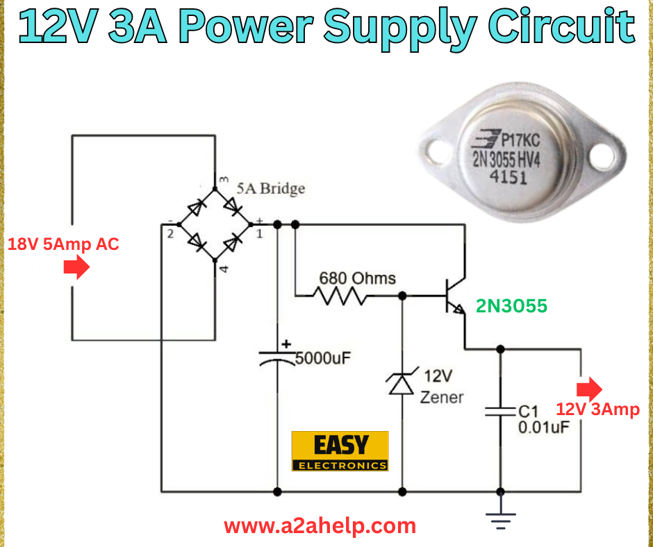
Are you looking to create a reliable 12V 3A power supply for your electronic projects? A well-designed power supply is the backbone of any circuit, ensuring stable and efficient performance. In this comprehensive guide, we’ll walk you through the process of building a 12V 3A power supply circuit, complete with a detailed analysis of the provided diagram. Whether you’re a hobbyist or a professional electronics engineer, this step-by-step tutorial will help you understand the components, assembly, and working principle of this circuit.
Understanding the 12V 3A Power Supply Circuit
The circuit diagram shown above is a simple yet effective design for a 12V 3A power supply. It converts an AC input into a regulated DC output, making it ideal for powering devices that require a steady 12V supply with a current capacity of up to 3A. Let’s break down the components and their roles in this circuit.
Components Required
- 18V 5A Transformer: Steps down the AC mains voltage to 18V AC.
- 5A Bridge Rectifier: Converts AC to DC by allowing current to flow in a single direction.
- 5000µF Capacitor: Smooths the rectified DC voltage by filtering out ripples.
- 680 Ohms Resistor: Biasing current for transistor.
- 12V Zener Diode: Regulates the output voltage to a stable 12V.
- 2N3055 Transistor: Acts as a pass element to handle the 3A current load.
- 0.01µF Capacitor (C1): Provides additional filtering for high-frequency noise.
- Heat Sink: Essential for dissipating heat generated by the 2N3055 transistor.
Circuit Diagram Analysis

- Input Stage: The 18V 5A transformer reduces the high-voltage AC from the mains to a safer 18V AC. This is fed into the 5A bridge rectifier, which converts the AC into pulsating DC.
- Smoothing: The 5000µF capacitor is connected across the rectifier output to smooth the pulsating DC into a more stable voltage, typically around 18-20V depending on the load.
- Regulation: The 12V Zener diode, in conjunction with the 680-ohm resistor, sets the reference voltage. The 2N3055 transistor amplifies this voltage and regulates the output to a constant 12V, capable of delivering up to 3A.
- Filtering: The 0.01µF capacitor (C1) further filters out any residual high-frequency noise, ensuring a clean DC output.
Step-by-Step Assembly Guide
- Prepare the Transformer: Connect the secondary winding of the 18V 5A transformer to the input of the bridge rectifier. Ensure proper insulation and secure connections.
- Install the Bridge Rectifier: Attach the rectifier to the circuit board, linking the AC input terminals to the transformer and the DC output to the capacitor.
- Add the Smoothing Capacitor: Solder the 5000µF capacitor across the positive and negative terminals of the rectifier output. Observe polarity to avoid damage.
- Connect the Regulator Circuit: Wire the 680-ohm resistor in series with the Zener diode. Connect the Zener diode’s cathode to the base of the 2N3055 transistor.
- Mount the Transistor: Attach the 2N3055 transistor to a heat sink to manage heat dissipation. Connect the collector to the positive line and the emitter to the output.
- Add the Filter Capacitor: Solder the 0.01µF capacitor across the output terminals for noise suppression.
- Test the Circuit: Before powering on, double-check all connections. Use a multimeter to verify the output is 12V and can handle a 3A load safely.
Working Principle
The circuit operates by first stepping down the AC mains voltage using the transformer. The bridge rectifier then converts this to DC, which is smoothed by the large capacitor. The Zener diode and 2N3055 transistor work together to regulate the voltage to a steady 12V. The transistor handles the current load, while the capacitors ensure a ripple-free output, making this an efficient power supply for various applications.
Safety Tips
- Always use a heat sink with the 2N3055 transistor to prevent overheating.
- Ensure proper grounding to avoid electrical shocks.
- Test the circuit with a low load initially to verify functionality.
Applications
This 12V 3A power supply is perfect for powering LED strips, small motors, audio amplifiers, and other DIY electronics projects requiring a stable DC voltage.
Conclusion
Building a 12V 3A power supply circuit is a rewarding project that enhances your understanding of electronics. By following this guide and using the provided diagram, you can create a reliable power source for your devices. For more electronics tutorials and circuit designs, visit www.a2ahelp.com. Have questions or need assistance? Feel free to leave a comment below!
