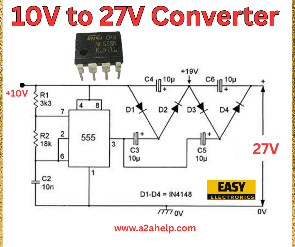
Are you looking to power devices that require a higher voltage than your current supply? A 10V to 27V converter circuit is an excellent DIY electronics project that can step up your voltage efficiently using a simple design. This guide will walk you through building your own voltage booster with the help of a clear circuit diagram. Perfect for hobbyists and professionals, let’s dive into the details!
What Is a 10V to 27V Converter?
A 10V to 27V converter is an electronic circuit that increases a 10V input to a stable 27V output, suitable for powering devices needing higher voltage. This project utilizes a 555 timer IC in a boost configuration, making it a reliable and cost-effective solution for voltage conversion.
Components You’ll Need
To create this 10V to 27V converter, gather the following materials:
- 555 Timer IC
- 1N4148 diodes (x4)
- 3.3kΩ resistor (R1)
- 18kΩ resistor (R2)
- 10nF capacitor (C2)
- 10µF capacitors (C3, C4, C5, C6)
- 10V DC power supply
- Connecting wires
- Soldering kit and breadboard (for prototyping)
Understanding the Circuit Diagram

- 555 Timer IC: Acts as the core oscillator to drive the boost converter.
- Resistors (R1 and R2): Set the timing and feedback for the oscillator.
- Capacitors (C2, C3, C4, C5, C6): Stabilize the circuit and filter the output voltage.
- Diodes (D1-D4): Form a voltage multiplier to step up the voltage.
- Power Supply: A 10V DC input powers the circuit, with the output reaching 27V.
Step-by-Step Construction Guide
Step 1: Set Up the 555 Timer Circuit
- Connect pin 1 of the 555 IC to ground and pin 8 to the 10V supply.
- Attach R1 (3.3kΩ) between pin 7 and the supply, and R2 (18kΩ) between pin 2 and pin 6.
- Link C2 (10nF) between pin 5 and ground for stability.
Step 2: Build the Voltage Multiplier
- Connect D1 and D2 in series, with the anode of D1 to the 555 output (pin 3).
- Add D3 and D4 in series, with the anode of D3 to the cathode of D2.
- Place C3 (10µF) between the cathode of D1 and ground, and C4 (10µF) between the cathode of D2 and ground.
- Connect C5 (10µF) between the cathode of D3 and ground, and C6 (10µF) between the cathode of D4 and the 27V output.
Step 3: Finalize and Test
- Wire the 10V DC power supply to the circuit.
- Measure the output across C6—if correctly assembled, you should get approximately 27V.
Benefits of a 10V to 27V Converter
- Versatile: Powers a wide range of devices requiring higher voltage.
- Efficient: Uses minimal components for a reliable boost.
- Cost-Effective: Affordable parts make it accessible for DIY projects.
Troubleshooting Tips
- Low Output: Check diode orientation and capacitor values.
- No Output: Ensure the 555 IC is properly connected and powered.
- Overheating: Verify resistor ratings to handle the current.
Why Choose This Project?
This 10V to 27V converter is ideal for electronics enthusiasts wanting to explore power conversion. With easily sourced components, you can build it in a short time, making it perfect for powering LED strips, small motors, or other high-voltage devices. It’s a great way to enhance your technical skills while meeting practical needs.
Conclusion
Building a 10V to 27V converter circuit is a rewarding project that combines simplicity with functionality. By following this guide and using the provided circuit diagram, you can create a reliable voltage booster for your electronics projects. Visit www.a2ahelp.com for more innovative electronics tutorials and start your DIY journey today!
