Are you looking to create a versatile power supply for your electronics projects? A 0V-300V variable power supply circuit is an excellent tool for testing and powering a wide range of devices. In this comprehensive guide, we’ll analyze the provided circuit diagram and walk you through building your own adjustable power supply. Ideal for hobbyists and professional engineers, this tutorial covers the components, assembly, and working principle to help you succeed.
Understanding the 0V-300V Variable Power Supply Circuit
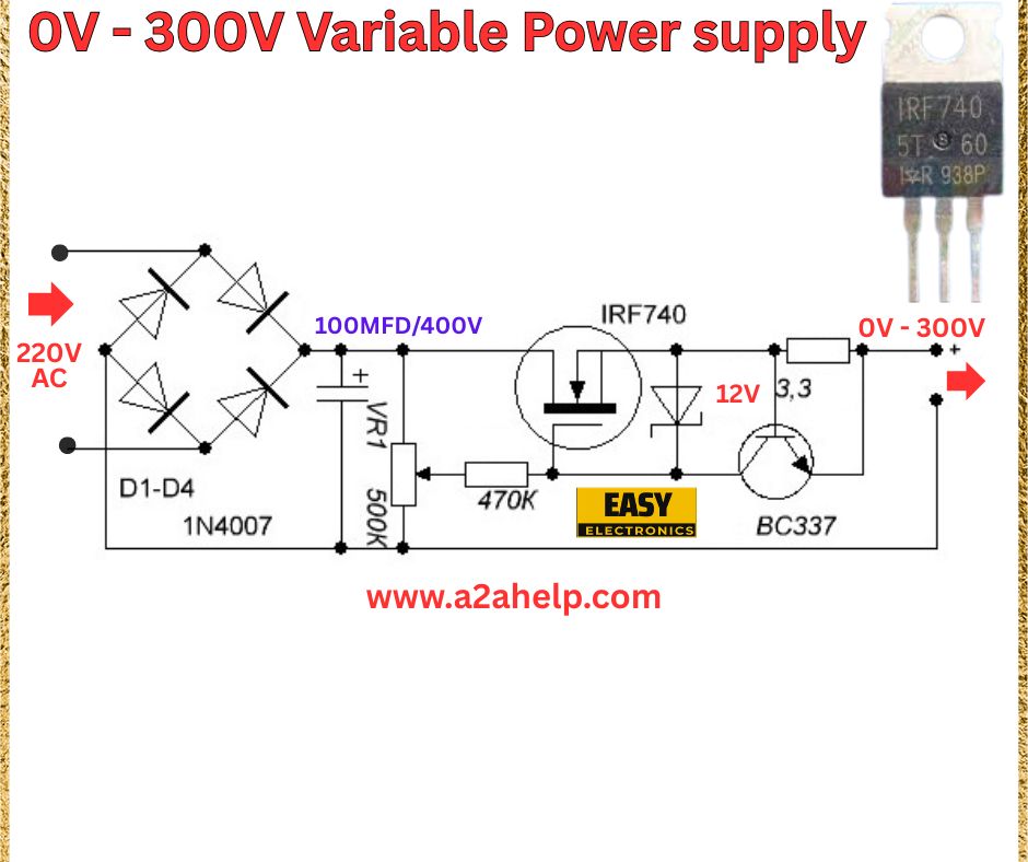
The circuit diagram above illustrates a variable power supply that converts 220V AC to a adjustable DC output ranging from 0V to 300V. This design uses a bridge rectifier, a MOSFET, and a transistor to regulate the output voltage, making it suitable for high-voltage applications. Let’s dive into the components and their roles in this circuit.
Components Required
- 220V AC Input: Provides the main power source.
- 1N4007 Diodes (D1-D4): Form a bridge rectifier to convert AC to DC.
- 100µF/400V Capacitor: Smooths the rectified DC voltage.
- IRF740 MOSFET: Acts as a pass element to control the output voltage.
- 12V 3.3Z Zener Diode: Sets the reference voltage for regulation.
- 470K Resistor (VR): Adjusts the gate voltage of the MOSFET.
- 50K Potentiometer: Fine-tunes the output voltage.
- BC337 Transistor: Amplifies the control signal to the MOSFET.

Circuit Diagram Analysis
- Rectification Stage: The 1N4007 diodes configured as a bridge rectifier convert the 220V AC input into pulsating DC.
- Smoothing Stage: The 100µF/400V capacitor filters the rectified DC, reducing ripples to provide a stable voltage.
- Regulation Stage: The BC337 transistor, driven by the 12V Zener diode and 50K potentiometer, controls the IRF740 MOSFET. The 470K resistor adjusts the gate voltage.
- Output Stage: The MOSFET regulates the output, allowing the voltage to be varied from 0V to 300V based on the potentiometer setting.
Step-by-Step Assembly Guide
- Set Up the Bridge Rectifier: Connect the four 1N4007 diodes in a bridge configuration. Link the AC input (220V) to the AC terminals and the DC output to the capacitor.
- Install the Capacitor: Solder the 100µF/400V capacitor across the positive and negative terminals of the rectifier output. Ensure correct polarity.
- Add the MOSFET and Transistor: Mount the IRF740 MOSFET and BC337 transistor on a heat sink. Connect the MOSFET’s drain to the positive line, source to the output, and gate to the transistor collector.
- Connect the Zener and Resistors: Attach the 12V Zener diode between the transistor base and ground. Solder the 470K resistor and 50K potentiometer in series with the gate circuit.
- Wire the Output: Link the output terminals to the MOSFET source and ground. Use a multimeter to test the voltage range.
- Test the Circuit: Power on the circuit and adjust the potentiometer to verify the output varies from 0V to 300V. Check for stability and heat dissipation.
Working Principle
The bridge rectifier converts 220V AC to DC, which is smoothed by the capacitor. The BC337 transistor, regulated by the Zener diode and potentiometer, controls the IRF740 MOSFET. By adjusting the potentiometer, you vary the gate voltage, allowing the MOSFET to regulate the output from 0V to 300V. This design ensures a stable and adjustable high-voltage supply.
Safety Tips
- Use a heat sink with the IRF740 MOSFET to prevent overheating.
- Work with insulated tools and ensure proper grounding to avoid electrical shocks.
- Test with a low load initially to confirm safe operation.
Applications
This variable power supply is perfect for testing high-voltage circuits, powering tube amplifiers, or experimenting with electronics projects requiring adjustable voltages.
Conclusion
Building a 0V-300V variable power supply circuit is a rewarding project that expands your electronics capabilities. By following this guide and using the provided diagram, you can create a reliable power source for your needs. For more electronics tutorials and projects, visit www.a2ahelp.com. Have questions? Leave a comment below!
