Voltage regulation is one of the most critical aspects of electronics design. Whether you’re building a small DIY electronics project, a power amplifier, LED driver, or any other circuit, maintaining a stable voltage output is essential for protecting components and ensuring reliable operation.
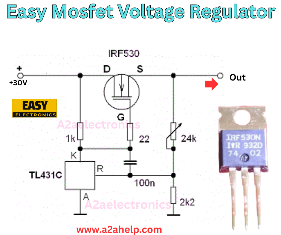
In this article, we’ll walk through a simple yet highly effective MOSFET-based voltage regulator circuit, as shown in the schematic diagram above. You’ll learn its working principle, the role of each component, design considerations, advantages, and how you can easily adapt it for your own electronic projects.
This is a well-optimized, SEO-friendly, and beginner-friendly guide designed to help hobbyists, students, and professionals understand how to build a linear voltage regulator using MOSFETs.
What is a MOSFET Voltage Regulator?
A MOSFET voltage regulator is a type of linear regulator that utilizes a MOSFET (Metal-Oxide-Semiconductor Field-Effect Transistor) as a pass element to control voltage. Unlike traditional regulators like the LM317 or 7805, this circuit provides flexibility, low dropout performance, and high current drive capability.
The regulator works by adjusting the MOSFET’s gate voltage based on a reference circuit (in this case, a TL431 shunt regulator IC), ensuring that the output voltage remains stable even when the input voltage fluctuates.
Circuit Components (Explained)
Let’s break down the parts in the given schematic:
- IRF530 MOSFET
- Acts as the main pass transistor to regulate the output voltage.
- Source (S) pin goes to output, Drain (D) pin connects to input (+30V), Gate (G) receives control signal.
- TL431 (Programmable Shunt Regulator)
- A highly accurate, adjustable voltage reference IC.
- Works like an “adjustable Zener diode” but with tighter tolerances.
- Ensures the feedback loop maintains the desired output voltage.
- Resistors (1k, 22Ω, 24k, 2.2k)
- Provide biasing and voltage divider functionality.
- 24k and 2.2k resistors form a divider that sets the reference voltage for TL431.
- 1k resistor limits current into TL431.
- 22Ω resistor is placed at the MOSFET gate to stabilize switching and prevent oscillations.
- Capacitor (100nF)
- Provides stability and noise filtering.
- Reduces unwanted oscillations from the MOSFET gate.

Working Principle of the MOSFET Voltage Regulator
Here’s a step-by-step working of the circuit:
- Input Power (+30V is applied)
A +30V DC source powers the circuit. This input can vary, but the regulator ensures a stable output at a lower voltage. - Voltage Divider & Reference Control
The 24kΩ and 2.2kΩ resistors act as a voltage divider, scaling down the output voltage. This scaled voltage is fed into the reference pin (R) of the TL431. - TL431 Regulation
The TL431 compares the divided voltage with its internal 2.5V reference. If the voltage is too high, TL431 conducts more current through its cathode pin (K), pulling the MOSFET gate down. - MOSFET Pass Element Control
The MOSFET (IRF530) operates as a variable resistor between the input and output. Its gate voltage, controlled by TL431, determines how much current flows from drain to source.- If the output voltage rises above the set point, TL431 drives the MOSFET gate lower, reducing conduction and stabilizing the output.
- If the output voltage falls below the desired level, TL431 reduces current conduction, allowing the MOSFET gate to rise and increase output current.
- Stable Output Achieved
This continuous feedback mechanism ensures that the output voltage remains constant, independent of variations in input voltage or load current changes.
Output Voltage Calculation
The output voltage is determined by the TL431 reference (2.5V) and the resistor divider formed by 24kΩ and 2.2kΩ resistors.
Vout=Vref×(1+R2R1)
Where:
Vref=2.5V
(TL431’s internal reference)
R1=24kΩ
R2=2.2kΩ
Vout=2.5×(1+24,000/2200)
Vout≈2.5×(1+10.9)≈2.5×11.9≈29.8V
So, the output voltage is approximately 29-30V, making it very close to the input supply. By changing resistor values, you can set different regulated outputs.
Advantages of MOSFET Voltage Regulators
- Low Dropout Voltage (LDO)
Since MOSFETs can operate in saturation with low resistance, this design allows for smaller voltage differences between input and output (ideal for LDO applications). - High Current Capacity
The IRF530 MOSFET can handle several amps of current, making this suitable for medium-to-high power circuits. - Flexible Output
By modifying the TL431 resistor divider, you can adjust the regulated voltage easily. - Simple and Cost-Effective
Uses only a handful of components compared to traditional regulator ICs. - Better Efficiency than Linear Regulators
Offers higher efficiency at lower voltage drop conditions compared to standard BJTs used in regulator circuits.
Applications
- Bench Power Supplies – Can regulate voltage for electronics testing.
- LED Drivers – Provide stable voltage to protect LEDs.
- Battery Chargers – Regulate current and voltage for safe charging.
- Industrial Electronics – Where stable supply rails are required.
- DIY Amplifier Projects – Protects audio circuits from fluctuating supply voltages.
Limitations
- Heat Dissipation: Being a linear regulator, excess energy will still dissipate as heat. A heatsink is required for the MOSFET at high currents.
- Not as Efficient as Switching Regulators: For high voltage drops, a buck converter would be more energy-efficient.
- Component Selection: MOSFET gate threshold and TL431 accuracy affect performance.
How to Build This Circuit
- Gather Components: IRF530 (or IRF530N), TL431, resistors (1k, 22Ω, 24k, 2.2k), 100nF capacitor, DC input source (+30V).
- Assemble on Breadboard or PCB: Place MOSFET properly with correct pinout (D-G-S).
- Heatsink the MOSFET: If drawing a heavy load, mount a heatsink.
- Test Output Voltage: Measure output with a multimeter and adjust resistors for the desired regulation value.
Conclusion
The Easy MOSFET Voltage Regulator circuit shown above is an excellent project for electronics beginners and professionals alike. It combines the power handling of MOSFETs with the precision of the TL431 programmable shunt regulator, resulting in a simple, cost-effective, and reliable voltage regulation solution.
By adjusting the resistor values, you can design regulators for a wide range of voltages. This makes it highly adaptable for use in DIY power supplies, audio amplifiers, battery chargers, and LED drivers.
If you’re looking for a robust, easy-to-build, and scalable voltage regulator, this design is a great starting point.
