Looking for a natural, chemical-free way to keep mosquitoes at bay? This DIY mosquito repellent circuit is a perfect electronics project for beginners and hobbyists alike. Using the versatile 555 timer IC, this circuit generates ultrasonic frequencies that repel mosquitoes without harmful chemicals. In this guide, we’ll break down the schematic, explain how it works, and provide a step-by-step guide to building your own mosquito repeller. Let’s get started!
What is a Mosquito Repellent Circuit?
A mosquito repellent circuit generates high-frequency sound waves, typically in the ultrasonic range (above 20 kHz), which are inaudible to humans but can deter mosquitoes. The circuit we’re exploring uses a 555 timer IC configured as an astable multivibrator to produce these frequencies, which are then emitted through a piezo buzzer. This is a safe, eco-friendly alternative to chemical repellents, ideal for outdoor activities or home use.
Understanding the Mosquito Repellent Circuit
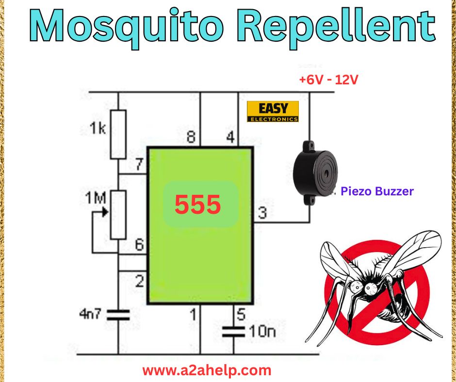
The schematic provided is a straightforward design that uses the 555 timer IC to create an ultrasonic signal. Here’s a breakdown of the circuit and its components:
- Power Supply: The circuit operates on a 6V to 12V DC supply, easily powered by batteries (e.g., a 9V battery).
- 555 Timer IC: The 555 IC is configured in astable mode to generate a continuous square wave signal.
- Resistors: A 1kΩ resistor and a 1MΩ resistor control the frequency and duty cycle of the oscillation.
- Capacitors: A 4.7nF capacitor (connected to pin 2) and a 10nF capacitor (connected to pin 5) set the timing and stabilize the 555 IC.
- Piezo Buzzer: The piezo buzzer converts the electrical signal into ultrasonic sound waves to repel mosquitoes.
This circuit is simple yet effective, making it an excellent project for learning about the 555 timer and its applications.
Components Needed for the Mosquito Repellent Circuit
Before you start building, gather these components:
- 555 Timer IC (1 unit)
- Piezo buzzer (ultrasonic-compatible)
- Resistors: 1kΩ (1), 1MΩ (1)
- Capacitors: 4.7nF (1), 10nF (1)
- 6V to 12V power supply (e.g., 9V battery)
- Breadboard or PCB for assembly
- Connecting wires
These components are affordable and widely available at electronics stores or online marketplaces.
How the Mosquito Repellent Circuit Works
Let’s break down the operation of this circuit in simple terms:
- Power Supply: The circuit is powered by a 6V to 12V DC source. A 9V battery is a common choice for portability.
- Astable Oscillation: The 555 timer IC is configured in astable mode, meaning it continuously oscillates between high and low states, producing a square wave. The frequency of this oscillation is determined by the 1kΩ resistor, 1MΩ resistor, and 4.7nF capacitor.
- The frequency can be approximated using the formula for a 555 timer in astable mode:

This frequency is in the ultrasonic range, ideal for repelling mosquitoes.
- The frequency can be approximated using the formula for a 555 timer in astable mode:
- Stabilization: The 10nF capacitor on pin 5 (control voltage) stabilizes the 555 timer, reducing noise in the output signal.
- Output: The square wave signal from pin 3 of the 555 IC drives the piezo buzzer, which converts the electrical signal into ultrasonic sound waves. These waves are inaudible to humans but can deter mosquitoes.
This design leverages the 555 timer’s versatility to create a simple, effective mosquito repellent.
Step-by-Step Guide to Build the Mosquito Repellent Circuit
Follow these steps to assemble the circuit:
- Set Up the Power Supply: Connect a 6V to 12V power source (e.g., a 9V battery). The positive terminal goes to the +6V/12V line, and the negative to the ground.
- Place the 555 Timer IC: Insert the 555 IC into your breadboard or PCB. Pin 1 is ground, and pin 8 connects to the positive supply.
- Connect the Timing Components:
- Connect the 1kΩ resistor between pin 7 (discharge) and pin 8 (Vcc).
- Connect the 1MΩ resistor between pin 7 (discharge) and pin 6 (threshold).
- Connect the 4.7nF capacitor between pin 6 (threshold) and ground.
- Connect pin 2 (trigger) directly to pin 6 (threshold).
- Add the Stabilization Capacitor: Connect the 10nF capacitor between pin 5 (control voltage) and ground.
- Attach the Piezo Buzzer: Connect one terminal of the piezo buzzer to pin 3 (output) of the 555 IC and the other terminal to ground.
- Power On and Test: Turn on the power supply. The piezo buzzer should emit an ultrasonic frequency (inaudible to humans). Test the circuit in an area with mosquitoes to verify its effectiveness.

Tips for Better Performance
- Power Supply Range: Use a 9V battery for optimal performance, as it balances power efficiency and output strength.
- Frequency Adjustment: If the circuit isn’t repelling mosquitoes effectively, adjust the frequency by changing the 4.7nF capacitor or the resistors. A smaller capacitor (e.g., 3.3nF) will increase the frequency.
- Buzzer Quality: Ensure the piezo buzzer is rated for ultrasonic frequencies (20 kHz and above) for best results.
- Placement: Place the circuit in an open area, as ultrasonic waves can be blocked by obstacles.
Why Build This Mosquito Repellent Circuit?
This DIY mosquito repellent circuit is a fun and practical project that introduces you to the 555 timer IC and its applications. It’s also a cost-effective, eco-friendly alternative to chemical repellents, making it perfect for camping, gardening, or home use. Once you’ve mastered this circuit, you can experiment with different frequencies or add a switch to control the device.
Conclusion
Building a mosquito repellent circuit using a 555 timer is a rewarding electronics project that combines simplicity with functionality. With just a few components, you can create an ultrasonic device to keep mosquitoes away naturally. Follow the steps in this guide, and you’ll have your own DIY mosquito repeller ready in no time. Stay bite-free and enjoy your electronics journey!
