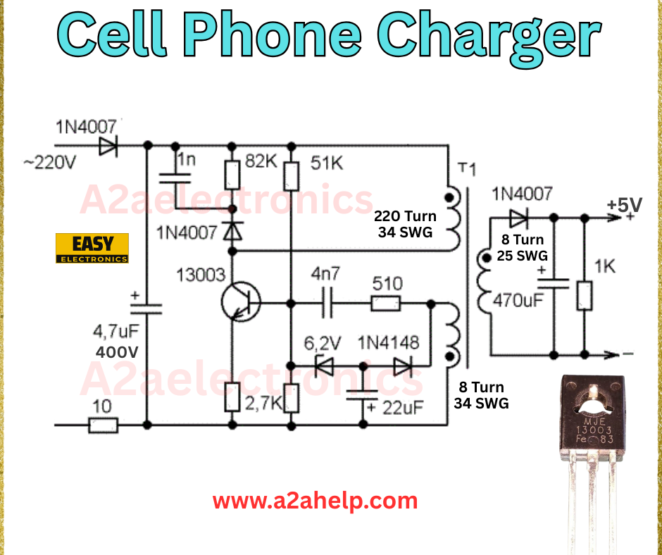
In today’s world, having a reliable cell phone charger is essential, and building your own can be a fun and educational project. This article explores a hand-drawn circuit diagram for a DIY cell phone charger that converts 220V AC to a stable 5V DC output. As an experienced electronics engineer, I’ll break down the components, explain how it works, and provide a practical guide to help you build it yourself. Whether you’re a hobbyist or looking to save money, this guide will set you on the right path.
What is a Cell Phone Charger Circuit?
A cell phone charger circuit transforms high-voltage alternating current (AC) from a wall outlet into the low-voltage direct current (DC) required to charge your device, typically 5V. The circuit in the image is a simple yet effective design using basic electronic components, making it accessible for beginners and intermediate enthusiasts alike.
Analyzing the Cell Phone Charger Circuit
Let’s dissect the diagram step by step:
- Input Stage (AC to DC Conversion)
- The circuit starts with a 220V AC input connected to a bridge rectifier made of four 1N4007 diodes. This converts AC to pulsating DC.
- A 4.7µF 400V capacitor smooths the rectified voltage, reducing ripple.
- Voltage Regulation
- A 13003 transistor acts as the main switching element, controlled by a 2.7kΩ resistor and a 510Ω resistor.
- A 6.2V 1N4148 Zener diode regulates the voltage, ensuring a stable output.
- A 22µF capacitor further filters the DC output for consistency.
- Transformer (T1)
- The transformer (T1) has two windings:
- 220 turns (34 SWG) on the primary side, stepped down from the rectified voltage.
- 8 turns (34 SWG) on the primary side its Auxilary winding.
- 8 turns (25 SWG) and 8 turns (34 SWG) on the secondary side, producing the lower voltage needed for charging.
- This step-down process is critical for safety and efficiency.
- The transformer (T1) has two windings:
- Output Stage
- The secondary winding connects to another 1N4007 diode for rectification.
- A 470µF capacitor and a 1kΩ resistor stabilize the final 5V output, ready to charge your phone.
- Current Limiting
- A 10Ω resistor for Inrush current limiter and 82kΩ and 51kΩ resistors in the feedback loop limit the current, protecting both the circuit and the phone.

How Does This Circuit Work?
The 220V AC input is rectified by the 1N4007 diodes and smoothed by the 4.7µF capacitor. The 13003 transistor, guided by the Zener diode and resistors, switches the voltage through the transformer. The secondary windings step down the voltage, which is then rectified and filtered to produce a steady 5V DC output. This design ensures safe and efficient charging for most cell phones.
Benefits of Building Your Own Charger
- Cost-Effective: Uses affordable, widely available components.
- Customizable: Adjust the transformer turns or resistors for different voltage needs.
- Educational: Offers hands-on learning about power conversion.
- Portable: Compact design fits easily into a small enclosure.
Step-by-Step Guide to Building the Charger
- Gather Components: Collect 1N4007 diodes, 13003 transistor, 1N4148 Zener diode, resistors, capacitors, and a transformer core.
- Assemble the Bridge Rectifier: Connect the four 1N4007 diodes in a bridge configuration.
- Wind the Transformer: Use 220 turns (34 SWG) for the primary, 8 turns (34 SWG) Aux (25 SWG/34 SWG) for the secondary on the T1 core.
- Connect the Circuit: Follow the diagram, ensuring correct polarity for diodes and capacitors.
- Test the Output: Use a multimeter to confirm a 5V output before connecting your phone.
- Enclose Safely: House the circuit in a non-conductive box with proper insulation.
Troubleshooting Tips
- No Output: Check the 220V input and diode orientation.
- Unstable Voltage: Verify the Zener diode and capacitor values.
- Overheating: Ensure the 10Ω resistor is correctly limiting current.
Conclusion
Building a DIY cell phone charger is a practical way to understand electronics while meeting your charging needs. This circuit, with its 1N4007 diodes, 13003 transistor, and custom transformer, delivers a reliable 5V output from a 220V source. Whether you’re experimenting or solving a power outage, this guide equips you with the knowledge to succeed. Check out more electronics projects on our site or share your build in the comments!
