Introduction to Battery Chargers with Auto Cut-Off
Maintaining the health of your batteries is crucial, whether for vehicles, solar systems, or backup power supplies. A 6V, 12V, or 24V battery charger with auto cut-off is an excellent solution to prevent overcharging and extend battery life. We’ll break down its components, functionality, and step-by-step guide to building your own, making it a must-read for electronics enthusiasts and DIYers.
What is a Battery Charger with Auto Cut-Off?
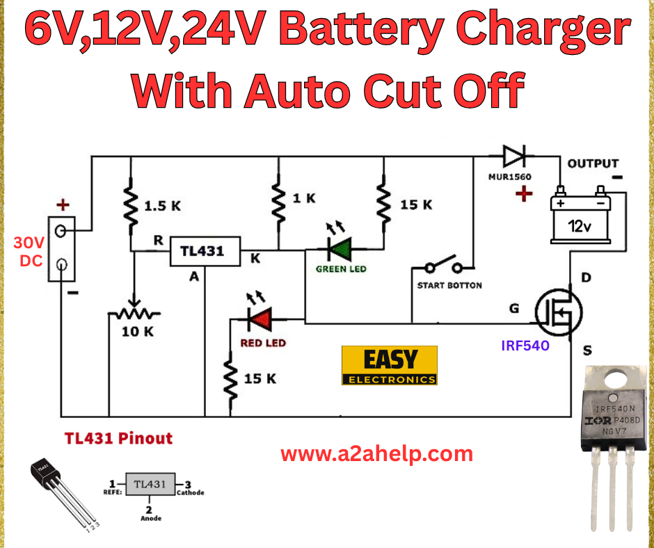
A battery charger with auto cut-off automatically stops charging once the battery reaches its full capacity, protecting it from damage. The circuit shown uses the TL431 voltage regulator and an IRF540 MOSFET to manage the charging process efficiently for 6V, 12V, and 24V batteries. This design is ideal for lead-acid batteries commonly found in cars, inverters, and UPS systems.
Analyzing the 6V, 12V, 24V Battery Charger Schematic
Key Components
- 30V DC Power Supply: Provides the input voltage to charge the battery.
- 1.5k and 1k Resistors: Form a voltage divider network to set the reference voltage for the TL431.
- TL431 Voltage Regulator: Acts as a precision shunt regulator to monitor and control the charging voltage.
- 10k Resistor: Connected to the TL431’s reference pin, it helps stabilize the voltage regulation.
- 15k Resistors: Used in the feedback loop and LED circuits for current limiting.
- Red and Green LEDs: Indicate charging status (red for charging, green for fully charged).
- Start Button: Manually initiates the charging process.
- MUR1560 Diode: Protects against reverse polarity and ensures current flows to the battery.
- IRF540 MOSFET: Acts as a switch to cut off the charging circuit when the battery is full.
- 12V Battery: The load being charged (adjustable for 6V or 24V with modifications).
Circuit Functionality

The circuit uses the TL431 to compare the battery voltage against a reference. When the battery voltage reaches the desired level (e.g., 13.8V for a 12V battery), the TL431 triggers the IRF540 MOSFET to disconnect the charging supply. The red LED lights up during charging, while the green LED indicates the auto cut-off when the battery is fully charged. The start button allows manual control to begin the process.
How the Auto Cut-Off Works
The TL431 monitors the battery voltage through the resistor network. Once the voltage exceeds the set threshold (adjustable via resistor values), it turns off the MOSFET, stopping the current flow. This prevents overcharging, a common issue that reduces battery lifespan. The LEDs provide a visual cue, making it user-friendly.
Advantages of This Battery Charger Design
- Versatility: Supports 6V, 12V, and 24V batteries with minor adjustments.
- Auto Cut-Off: Protects batteries from overcharging.
- Cost-Effective: Uses affordable components like the TL431 and IRF540.
- Simple Design: Easy to assemble for hobbyists with basic electronics skills.
Limitations
- Manual Start: Requires pressing the start button to initiate charging.
- Voltage Adjustment: May need recalibration for different battery types or capacities.
Applications of the 6V, 12V, 24V Battery Charger
This charger is perfect for:
- Automotive Use: Charging car or motorcycle batteries.
- Solar Power Systems: Maintaining backup batteries.
- Home UPS: Ensuring uninterrupted power supply readiness.
Building Your Own Battery Charger with Auto Cut-Off
Materials Needed
- 30V DC power supply
- TL431 voltage regulator
- IRF540 MOSFET
- 1.5k, 1k, 10k, and 15k resistors
- MUR1560 diode
- Red and green LEDs
- Start button
- Connecting wires and breadboard
Step-by-Step Guide
- Connect the 30V DC supply to the input terminals.
- Wire the 1.5k and 1k resistors to form a voltage divider, linking to the TL431’s reference pin.
- Attach the 10k resistor and red LED to the TL431 for charging indication.
- Connect the 15k resistor and green LED to signal the auto cut-off.
- Install the MUR1560 diode and IRF540 MOSFET in the output path to the battery.
- Add the start button to control the charging initiation.
- Test the circuit with a 12V battery, adjusting resistor values for 6V or 24V as needed.
Always use a multimeter to verify voltages and ensure proper connections. For detailed schematics, check www.a2ahelp.com.
Safety Tips
- Wear protective gear when handling circuits.
- Avoid short circuits by double-checking wiring.
- Use a fuse to protect against overcurrent.
Conclusion
Building a 6V, 12V, or 24V battery charger with auto cut-off is a rewarding project that enhances your electronics skills while providing a practical tool. The circuit from Easy Electronics offers a reliable design to safeguard your batteries. Explore more DIY electronics projects on our site, and share your experiences with us!
