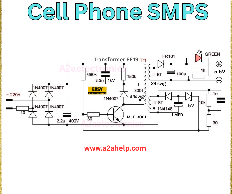
The Cell Phone SMPS (Switched Mode Power Supply) is a compact, efficient, and reliable power conversion circuit designed to provide a stable 5V to 5.5V DC output for charging mobile devices. This circuit uses minimal components yet delivers high efficiency and low heat generation.
Understanding the Circuit Design
This SMPS circuit works on the principle of high-frequency switching and transformer isolation. The AC mains voltage (~220V) is rectified and filtered, then switched at high speed through a transistor-driven transformer. The output is rectified and filtered again to supply a steady low-voltage DC for mobile charging.
Key Components and Their Roles
- 1N4007 Diodes: Form a bridge rectifier to convert AC mains into DC.
- 2.2µF/400V Capacitor: Smoothens the rectified DC to reduce ripple.
- MJE13001 Transistor: Works as a high-speed switch to control transformer pulses.
- EE19 Transformer: Provides isolation and steps down the voltage.
- FR101 Diode: Fast recovery diode for output rectification.
- 1N4148 Diode: Used for feedback and regulation control.
- 100µF Capacitor: Smooths the output voltage for a stable supply.
- LED Indicator: Shows the charger’s operational status.

Working Principle
- AC Input Rectification – The AC mains passes through four 1N4007 diodes, creating a full-wave rectified DC voltage.
- Filtering – The 2.2µF/400V capacitor filters high-frequency noise from the rectified DC.
- Switching & Transformation – The MJE13001 transistor switches the DC at high frequency, energizing the EE19 transformer.
- Voltage Step-Down & Rectification – The transformer’s secondary outputs a low AC voltage, which is rectified by FR101 or 1N4148 diodes.
- Output Filtering & Regulation – Capacitors smooth the voltage, and the feedback system ensures a stable output of 5V to 5.5V.
Advantages of This SMPS Design
- High efficiency and low heat dissipation
- Compact and lightweight design
- Isolated output for safety
- Low component count and easy assembly
- Stable voltage regulation for sensitive devices
Applications
- Mobile phone charging
- Small electronic gadgets
- Portable power supplies
- LED lighting power source
Safety Precautions
- Handle only when disconnected from mains power
- Use proper insulation around high-voltage areas
- Test with a load to avoid damage to components
- Avoid moisture and short circuits during operation
Conclusion
This Cell Phone SMPS circuit is an ideal low-cost and efficient power solution for charging devices. Its high-frequency switching operation ensures minimal power loss while maintaining a stable and safe output. With careful assembly and safety precautions, it can be a reliable project for electronics enthusiasts and repair technicians.
