Are you an electronics enthusiast looking to dive into a fun and educational project? Building a 2 Transistor AM Radio Receiver is an excellent way to get hands-on experience with basic circuitry while creating a functional device. This simple yet effective design, sourced from A2aelectronics, uses minimal components to pick up AM radio signals. In this comprehensive guide, we’ll walk you through the circuit diagram, components, and steps to build your own AM radio receiver. Let’s get started!
Understanding the 2 Transistor AM Radio Receiver
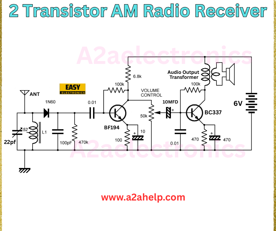
The 2 Transistor AM Radio Receiver is a classic project that demonstrates the principles of amplitude modulation (AM) radio reception. This circuit uses just two transistors—BF194 and BC337—to amplify and demodulate AM signals, making it an ideal beginner project. With a 6V power supply and a few passive components, you can tune into your favorite AM stations with ease.
Key Components of the Circuit
- Transistors: BF194 (RF amplifier) and BC337 (audio amplifier)
- Inductor (L1): Tuned with a 22pF capacitor for AM frequency selection
- Capacitors: 100pF, 0.01µF, and 10µF for coupling and filtering
- Resistors: 470kΩ, 100Ω, 6.8kΩ, and 100kΩ for biasing and volume control
- Diode (1N60): For signal detection
- Audio Output Transformer: Connects to a speaker
- Antenna (ANT): Captures radio waves
- 6V Power Supply: Provides the necessary voltage

Step-by-Step Guide to Building the AM Radio Receiver
1. Gather Your Materials
Before starting, ensure you have all the components listed above. You can source these from any electronics supplier or repurpose parts from old devices. A breadboard and soldering iron will also be handy for prototyping and assembly.
2. Analyze the Circuit Diagram
The provided image from A2aelectronics shows a clear schematic. The BF194 transistor acts as the RF amplifier, picking up signals via the antenna and tuning them with the L1 inductor and 22pF capacitor. The 1N60 diode demodulates the signal, which is then amplified by the BC337 transistor. The 100kΩ potentiometer serves as a volume control, and the audio output transformer drives the speaker.
3. Assemble the Circuit
- Connect the antenna to the input of the BF194 transistor.
- Link the 22pF capacitor and L1 inductor in parallel to tune the AM frequency.
- Use the 100pF and 0.01µF capacitors for coupling between stages.
- Bias the transistors with the 470kΩ and 100Ω resistors.
- Attach the 10µF capacitor and 6.8kΩ resistor to the BC337 for audio amplification.
- Connect the audio output transformer to a speaker and link the 6V power supply.
4. Test and Tune
Power up the circuit and adjust the volume control. Move the antenna to improve signal reception. Fine-tune the L1 inductor to lock onto your desired AM station. If the sound is weak, double-check your connections and component values.
Benefits of Building a 2 Transistor AM Radio
- Educational Value: Learn about AM signal processing, transistor amplification, and circuit design.
- Cost-Effective: Uses affordable and readily available components.
- Portable Design: Compact enough to carry or modify for personal use.
Troubleshooting Tips
- No Sound: Ensure the power supply is connected correctly and the speaker is functional.
- Weak Signal: Adjust the antenna position or replace the 22pF capacitor for better tuning.
- Distortion: Check for loose connections or incorrect resistor values.
Why Choose This Project?
This 2 Transistor AM Radio Receiver project is perfect for hobbyists and students alike. It’s a stepping stone to more complex radio designs and offers a satisfying reward when you hear your first broadcast. Plus, it’s a great way to understand the fundamentals of electronics in a hands-on manner.
Conclusion
Building a 2 Transistor AM Radio Receiver is a rewarding DIY project that combines learning with creativity. With the detailed circuit diagram from A2aelectronics and this guide, you’re well on your way to success. Grab your tools, follow the steps, and tune into the airwaves! For more electronics projects and tutorials, visit www.a2ahelp.com.
