Hey, if you’ve been tinkering with electronics and come across bipolar junction transistors, or BJTs, you know they’re versatile little devices. But the way you connect them—known as configurations—can change everything about how they perform. The image you shared breaks it down nicely, showing the three main setups: common emitter, common base, and common collector, for both NPN and PNP types. It includes symbols with input and output signals, plus photos of real transistors like the 2N3055 and 2N2955 for common emitter, TIP35C and TIP36C for common base, and BD139 and BD140 for common collector. As an electronics engineer with years of building circuits, I’ll analyze this image and explain each configuration in detail. We’ll cover how they work, their characteristics, applications, and even some math to back it up. By the end, you’ll know which one to pick for your next project. Let’s start with the basics.
What Are BJT Configurations and Why Do They Matter?
A BJT has three terminals: base, collector, and emitter. The “configuration” refers to which terminal is common between the input and output. This common point is usually grounded or shared, affecting the transistor’s gain, impedance, and phase relationship between input and output.
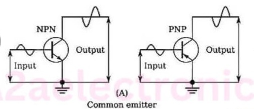
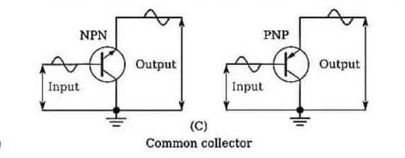
In the image, it’s labeled (A) Common Emitter, (B) Common Base, and (C) Common Collector. For each, there’s an NPN symbol on the left and a PNP on the right, with wavy lines showing input at one terminal and output at another. The waveforms suggest amplification or buffering, with the output often inverted or in phase depending on the setup.
Why care? Each configuration suits different needs. Common emitter is great for amplification with high gain, common base for high-frequency work, and common collector for buffering with unity gain but high current drive. The image pairs them with power transistors, hinting at practical uses in amplifiers or switches.
NPN transistors, like the 2N3055, conduct when the base is positive relative to the emitter. PNP, like the 2N2955, are the opposite—base negative to emitter. The image shows both to remind us that configurations apply to either, though polarities flip.
From datasheets, the 2N3055 is an NPN power transistor with a collector-emitter voltage (VCEO) of 60V and continuous collector current (Ic) up to 15A. Its PNP complement, the 2N2955, handles similar power but with reversed polarities, often used in push-pull amplifiers. These are classic choices for common emitter setups in audio amps.
Moving on, let’s dig into each configuration.
Common Emitter Configuration: The Workhorse for Amplification
The common emitter setup is the most popular, and it’s labeled (A) in the image. Here, the emitter is common (grounded), the input goes to the base, and output comes from the collector. For NPN, the symbol shows the arrow on the emitter pointing out, with input signal at the base and output at the collector, inverted waveform indicating 180-degree phase shift.
In operation, a small base current controls a larger collector current. The current gain, beta (β), is Ic / Ib, typically 20-200 for power transistors like those shown. Voltage gain is high too, Av = – (Rc / Re), where Rc is collector resistor and Re emitter resistor.

Characteristics:
- High voltage and current gain
- Medium input impedance (around 1kΩ to 5kΩ)
- Low output impedance (tens of kΩ)
- Phase inversion: Output is 180 degrees out of phase with input
For PNP, it’s similar but with negative voltages. The image pairs it with 2N3055 (NPN) and 2N2955 (PNP), both TO-3 packaged for heat dissipation. The 2N3055 can dissipate up to 115W, making it ideal for linear power supplies or audio amplifiers.
Applications: Audio amplifiers, signal amplification in radios, switching in logic circuits. In a basic amplifier, bias the base with resistors to set quiescent point, add coupling caps for AC signals. For example, with Vcc=12V, Rc=1kΩ, Re=100Ω, gain is about -10.
Pros: Versatile, high gain. Cons: Can be unstable without feedback, phase inversion might need compensation.
To calculate bias: Use voltage divider on base for stability. Vb = Vcc * (R2 / (R1 + R2)), then Ve = Vb – 0.7V, Ie = Ve / Re, Ic ≈ Ie.
In tutorials, common emitter is often the first taught because it’s straightforward for amplification. You can simulate it in software like LTSpice to see the inverted output.
Common Base Configuration: For High-Frequency and Low-Noise Apps
Labeled (B) in the image, common base has the base as the common terminal. Input is at the emitter, output at the collector. The symbol shows input signal at emitter, output at collector, with no phase inversion—the waveform is in phase.
This setup has voltage gain but current gain less than 1 (alpha, α = Ic / Ie ≈ 0.98). Voltage gain Av = Rc / Re, positive.

Characteristics:
- Low input impedance (tens of Ω)
- High output impedance (hundreds of kΩ)
- High voltage gain, low current gain
- No phase inversion
- Excellent high-frequency response (low Miller capacitance)
The image uses TIP35C (NPN) and TIP36C (PNP), medium-power transistors. The TIP35C has VCEO 100V, Ic 25A continuous, power dissipation 125W. TIP36C is the PNP version, similar specs. These are often in common base for RF amplifiers or current buffers.
Applications: RF amplifiers, impedance matching in antennas, cascode stages for high bandwidth. In a cascode, common base tops a common emitter for better frequency response.
Pros: Stable, high bandwidth (up to GHz in RF BJTs), low noise. Cons: Low input impedance makes driving hard, no current gain.
Biasing: Base at fixed voltage, emitter resistor for current set. Input signal couples to emitter. For example, with Vcc=12V, Rc=2kΩ, emitter input via cap.
In practice, common base is less common for audio but shines in microwave circuits where capacitance matters.
Common Collector Configuration: The Buffer King
(C) in the image is common collector, also called emitter follower. Collector is common (tied to supply), input at base, output at emitter. Waveform shows output following input, in phase.
Voltage gain is nearly 1 (Av ≈ 1), but current gain is high (β + 1). It’s a buffer.
Characteristics:
- High input impedance (hundreds of kΩ)
- Low output impedance (tens of Ω)
- Unity voltage gain, high current gain
- No phase inversion
- Good bandwidth

The image features BD139 (NPN) and BD140 (PNP), medium-power in TO-126 package. BD139: VCEO 80V, Ic 1.5A, power 12.5W. BD140 similar for PNP. Great for buffers in audio preamps.
Applications: Voltage buffers, impedance matching, level shifting, driving loads like speakers or relays.
Pros: High input Z protects source, low output Z drives loads, linear. Cons: No voltage gain, needs higher input voltage.
Biasing: Base divider, emitter resistor for output. Output voltage follows input minus 0.7V.
For example, in a push-pull output stage, use NPN and PNP in common collector for low distortion.
Tutorials often show it as a follower for unity gain buffering.
Comparing the Three Configurations
To choose, consider your needs. Here’s a table:
| Configuration | Voltage Gain | Current Gain | Input Z | Output Z | Phase | Common Uses |
|---|---|---|---|---|---|---|
| Common Emitter | High (-Rc/Re) | High (β) | Medium | Medium | Inverted | Amplifiers, switches |
| Common Base | High (Rc/Re) | Low (<1) | Low | High | In phase | RF amps, cascodes |
| Common Collector | Low (~1) | High (β+1) | High | Low | In phase | Buffers, drivers |
From the image, power transistors suggest focusing on higher current apps, like the 2N3055 in common emitter for power amps.
NPN vs PNP: NPN generally faster due to electron mobility, PNP for symmetry in complementary circuits.
Real-World Examples and Transistors from the Image
The image highlights specific BJTs:
- Common Emitter: 2N3055 (NPN), 2N2955 (PNP). Use in audio power amps. For instance, a 2N3055 in common emitter with 50V supply can drive speakers.
- Common Base: TIP35C (NPN), TIP36C (PNP). In RF, TIP35C handles 25A for high-power matching.
- Common Collector: BD139 (NPN), BD140 (PNP). In voltage regulators or audio drivers, BD139 buffers op-amp outputs.
Datasheets show these are epitaxial silicon, good for linearity.
Build a simple common emitter amp: Transistor base to 10k/4.7k divider from 12V, collector 1k to 12V, emitter 100Ω to ground. Input cap 1uF to base, output cap from collector.
Biasing and Stability in BJT Configurations
Biasing sets the operating point. For common emitter, class A uses resistor divider for thermal stability.
In common base, fixed base voltage, emitter resistor.
Common collector similar to emitter.
Use h-parameters for analysis: hfe = β, hie input Z, etc.
For stability, add emitter resistor to reduce gain but improve linearity.
Modern Applications in 2025
Even with MOSFETs dominant, BJTs hold in RF (common base), audio (common emitter), and discrete logic. In 2025, SiGe BJTs push frequencies higher for 5G.
Hybrid circuits use common collector to drive MOSFETs.
Troubleshooting and Tips
Distortion? Check bias. No gain? Wrong config. Heat? Add heatsink.
Test with multimeter: Vbe 0.7V forward.
Conclusion
The image captures BJT essentials perfectly. Common emitter for gain, base for speed, collector for buffering. With transistors like 2N3055, you see real-world power handling. Experiment—start with common emitter on breadboard. You’ll appreciate their simplicity.
