Introduction to 12V Switch Mode Power Supplies (SMPS)
A 12V Switch Mode Power Supply (SMPS) is a highly efficient solution for powering electronic devices, offering a compact design and low energy loss compared to linear power supplies. This article explores a 12V SMPS circuit that repurposes an AT/ATX transformer, utilizing the IR2153 driver IC and IRF740 MOSFETs to deliver a stable 12V DC output. This design is ideal for applications like powering LEDs, microcontrollers, or other 12V devices.
Circuit Overview: How Does a 12V SMPS with AT/ATX Transformer Work?
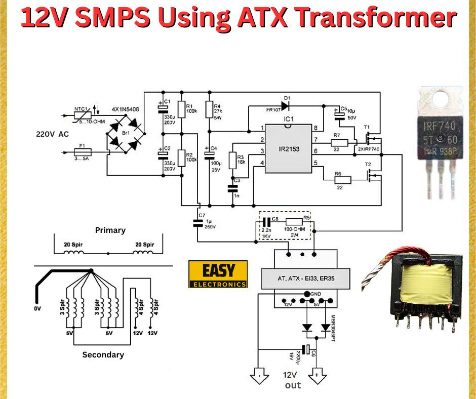
This SMPS circuit converts a 220V AC input into a regulated 12V DC output using a half-bridge topology. The AT/ATX transformer, originally designed for computer power supplies, is repurposed here, with the IR2153 IC driving two IRF740 MOSFETs for high-frequency switching. The circuit includes input protection, filtering, and feedback mechanisms to ensure stable operation.
Key Components of the 12V SMPS Circuit
- Input Protection and Filtering:
- NTC1 (5Ω, 10Ω): A Negative Temperature Coefficient thermistor limits inrush current during startup.
- F1 (3.15A Fuse): Protects the circuit from overcurrent conditions.
- 4x 1N5408 Diodes (B1): Form a bridge rectifier, converting 220V AC to pulsating DC.
- C1, C2 (330µF, 200V): Smooth the rectified DC, providing a stable input to the switching stage.
- IR2153 Driver IC:
- The IR2153 is a self-oscillating half-bridge driver IC, commonly used in SMPS designs.
- It generates high-frequency square waves to drive the MOSFETs, with its frequency set by R1 (1kΩ) and C4 (100µF).
- Switching MOSFETs (IRF740):
- Two IRF740 MOSFETs, rated for 400V and 10A, handle the high-frequency switching.
- They drive the primary winding of the transformer in a push-pull configuration.
- AT/ATX Transformer (T1):
- Primary: 20 +20 turns (split into two 20-turn sections).
- Secondary: Outputs 0V, 5V, and 12V with 3, 4, and 5 turns, respectively.
- The transformer steps down the high-voltage AC from the primary to a lower voltage on the secondary side.
- Output Stage:
- D1 (FR107): A fast-recovery diode rectifies the 12V output.
- C9 (1000µF, 25V): Smooths the rectified 12V output.
- C8 (1kΩ, 0.1µF): Provides additional filtering to reduce ripple.
- Feedback and Control:
- R6, R7 (22Ω): Limit current to the MOSFET gates.
- C7 (1µF, 25V): Stabilizes the IR2153’s operation.

How the 12V SMPS Circuit Works
- AC to DC Conversion:
- The 220V AC input is rectified by the 1N5408 bridge (B1) into pulsating DC.
- Capacitors C1 and C2 (330µF, 200V) smooth this voltage, providing a stable DC input of approximately 310V (220V × √2).
- High-Frequency Switching:
- The IR2153 IC generates a high-frequency square wave (typically 20-100 kHz, depending on R1 and C4 values).
- This signal drives the IRF740 MOSFETs, which alternately switch the primary winding of the transformer, creating an AC voltage across it.
- Voltage Transformation:
- The AT/ATX transformer steps down the high-voltage AC to lower voltages on the secondary side.
- The 12V winding (5 turns) produces the desired output, while the 5V winding (4 turns) could be used for additional outputs if needed.
- Output Regulation:
- The FR107 diode rectifies the 12V AC from the secondary winding into DC.
- Capacitor C9 (1000µF, 25V) smooths the output, delivering a stable 12V DC with minimal ripple.
Practical Tips for Building a 12V SMPS with AT/ATX Transformer
- Transformer Rewinding:
- AT/ATX transformers are designed for specific voltages. Ensure the primary and secondary turns match the design (20+20 turns primary, 5 turns for 12V secondary).
- Use proper insulation between windings to maintain safety and prevent arcing.
- Heat Management:
- The IRF740 MOSFETs will generate heat during switching. Mount them on heatsinks to prevent thermal failure.
- The IR2153 IC may also require a small heatsink if operating at high frequencies or loads.
- Safety Precautions:
- The primary side operates at high voltage (220V AC). Use an isolated enclosure and ensure proper grounding.
- Add a varistor across the AC input for surge protection.
- Component Selection:
- Ensure C1 and C2 are rated for at least 200V to handle the rectified voltage (310V peak).
- The FR107 diode should be replaced with a Schottky diode (e.g., SB560) for better efficiency if higher currents are expected.
Applications of a 12V SMPS
- LED Lighting: Powers 12V LED strips or modules.
- Microcontroller Projects: Supplies stable voltage for Arduino or Raspberry Pi setups.
- Battery Charging: Charges 12V lead-acid batteries with appropriate current limiting.
Conclusion
This 12V SMPS circuit, utilizing an AT/ATX transformer, IR2153 driver, and IRF740 MOSFETs, offers an efficient and compact solution for powering 12V devices. Its half-bridge topology ensures high efficiency, while the repurposed transformer makes it a cost-effective project for hobbyists. By following the design tips and ensuring safety, you can build a reliable 12V power supply for various applications.
Keywords
- 12V SMPS circuit
- AT/ATX transformer power supply
- IR2153 driver IC
- IRF740 MOSFET SMPS
- Efficient 12V power supply design
- smps

