Introduction
A variable DC power supply capable of delivering 0-300V is a valuable tool in electronics for testing circuits, powering high-voltage devices, or conducting experiments. This article analyzes a simple high-voltage power supply circuit using an IRF740 MOSFET, focusing on its components, operation, and practical considerations.
Circuit Overview
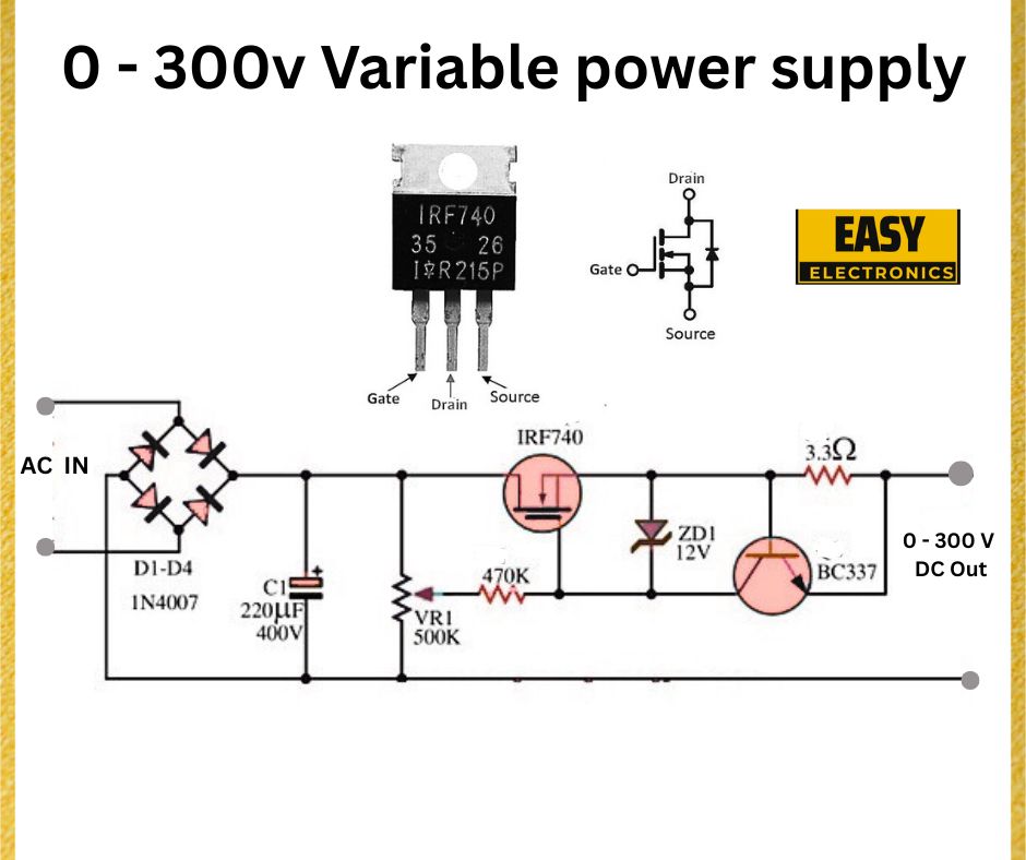
The circuit converts an AC input into a variable DC output ranging from 0 to 300V. Key components include a bridge rectifier, an N-channel MOSFET (IRF740), a variable resistor for voltage control, and protective elements like a Zener diode.

Components Breakdown
- Bridge Rectifier (D1-D4, IN4007):
- Four IN4007 diodes form a full-wave bridge rectifier, converting the AC input to pulsating DC.
- The IN4007 diode is rated for 1000V and 1A, suitable for handling high voltages but limited in current capacity.
- Capacitor (C1, 220µF, 400V):
- C1 smooths the pulsating DC from the rectifier into a more stable DC voltage.
- Rated at 400V, it can handle the rectified voltage, which could approach 300V RMS × √2 ≈ 424V peak (before regulation).
- MOSFET (IRF740):
- The IRF740 is an N-channel MOSFET with a voltage rating of 400V and a current rating of 10A.
- It acts as a voltage regulator, controlling the output voltage by adjusting the resistance between its drain and source based on the gate voltage.
- Variable Resistor (VR1, 470kΩ):
- VR1 adjusts the gate voltage of the IRF740, allowing the output voltage to vary from 0 to 300V.
- A high resistance value (470kΩ) ensures fine control over the gate voltage.
- Zener Diode (ZD1, 12V):
- ZD1 protects the MOSFET gate by clamping the gate-source voltage to 12V, preventing damage from overvoltage.
- The IRF740’s maximum gate-source voltage is typically ±20V, so the 12V Zener keeps it within safe limits.
- Transistor (BC337):
- The BC337 NPN transistor likely serves as a feedback or control element, though its exact role in this simplified schematic is unclear without further context.
- It may assist in stabilizing the output or protecting the circuit.
- Load Resistor (3.3Ω):
- A 3.3Ω resistor at the output represents the load or a current-limiting element.
- Its low value suggests the circuit is designed for low-current applications.
Operation
- AC to DC Conversion:
- The AC input is rectified by the bridge (D1-D4) into a pulsating DC voltage.
- C1 filters this voltage, providing a relatively smooth DC input to the MOSFET.
- Voltage Regulation:
- The IRF740 MOSFET operates in its linear region, acting as a variable resistor.
- Adjusting VR1 changes the gate voltage of the IRF740, which in turn adjusts the voltage drop across the MOSFET’s drain source, controlling the output voltage.
- At minimum resistance (VR1 = 0Ω), the gate voltage is low, the MOSFET is off, and the output voltage approaches 0V.
- At maximum resistance, the gate voltage increases, turning the MOSFET fully on, and the output voltage approaches the rectified input (up to 300V, limited by circuit losses and component ratings).
- Protection:
- ZD1 ensures the gate-source voltage of the IRF740 does not exceed 12V, protecting the MOSFET.
- The BC337 transistor may provide additional feedback or protection, though its role requires further clarification.
Practical Considerations
- Heat Dissipation:
- The IRF740 will dissipate significant power in the linear region, especially at high voltage drops (e.g., when outputting 50V from a 400V input). A heatsink is essential to prevent thermal failure.
- Power dissipation can be estimated as P = (V_in – V_out) × I_load. For a 1A load at 50V output, P = (400V – 50V) × 1A = 350W, which is impractical without robust cooling.
- Current Limitations:
- The IN4007 diodes and the 3.3Ω load resistor suggest this circuit is designed for low-current applications (likely below 1A).
- For higher currents, components like the diodes, capacitors, and MOSFET would need to be upgraded.
- Safety:
- Working with 300V DC poses significant safety risks. Proper insulation, grounding, and enclosures are critical to prevent electrical shock.
- The circuit lacks overcurrent or short-circuit protection, which should be added for practical use.
- Component Ratings:
- The IRF740 (400V rating) is operating near its limit with a rectified input of ~424V peak. A MOSFET with a higher voltage rating (e.g., 600V) would provide a better safety margin.
- C1’s 400V rating is also close to the peak input voltage, so a 450V or 500V capacitor would be safer.
Conclusion
This 0-300V variable DC power supply circuit is a simple design for low-current, high-voltage applications. It leverages the IRF740 MOSFET for voltage regulation, with a bridge rectifier and smoothing capacitor providing the DC input. While functional, the circuit has limitations in current capacity, heat dissipation, and safety features. For practical use, enhancements like better component ratings, thermal management, and protection mechanisms are recommended.
