Hey, if you’ve ever needed to top up a small Li-ion battery from a USB port without all the bells and whistles of a fancy charger, this circuit might be just what you’re looking for. It’s super basic, uses a BC558 PNP transistor as the main player, and keeps the component count low. Think of it as a trickle charger for things like 3.7V cells from old gadgets or DIY projects. It’s not meant for high-capacity 18650s that need fast charging, but for smaller stuff, it’s reliable and easy to build. I’ll break it down for you, like we’re chatting about it over a workbench.
Li-ion batteries need careful handling—they like to be charged to about 4.2V max, with current that’s not too aggressive to avoid heat or damage. This circuit takes 5V from USB and delivers a low current, around 5 to 10 mA, depending on the battery state, which is safe for slow charging. There’s no automatic cutoff here, so you’ll want to keep an eye on the voltage with a multimeter to pull it when it hits 4.2V. But the design includes some basic protection and an indicator to let you know things are happening.
Understanding the Circuit
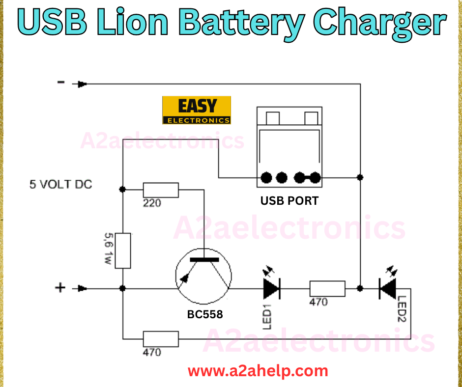
The schematic is pretty straightforward. The input comes from a 5V DC source, like a USB port or adapter. The positive line goes through a 220Ω resistor rated at 0.5W to limit the current and prevent spikes. From there, it hits the collector of the BC558 PNP transistor. The emitter connects directly to the positive terminal of your Li-ion battery, and the base is biased to ground through a 470Ω resistor, which turns the transistor on when power is applied.
Then there’s this branch from the base: it goes through diode D1, another 470Ω resistor, and LED2 back to the battery positive. I think D1 is there for protection, maybe to block reverse current if the battery is connected wrong, or to drop voltage for the indicator. LED2 acts as a status light— it glows when charging is active, giving you a visual cue. The negative from the USB connects straight to the battery negative, completing the loop.
Overall, it’s a linear setup where the transistor passes current from USB to the battery, limited by that 220Ω resistor. No ICs, no complexity, just analog basics.

Components You’ll Need
Here’s what to grab—most of this is stuff you probably have in your parts bin:
- BC558 PNP transistor (common, cheap, handles up to 100mA easily)
- Resistors: 220Ω (0.5W for safety), two 470Ω (1/4W is fine)
- Diode D1 (likely a 1N4148 or 1N4001 for general purpose)
- LED2 (any standard LED, like red for charging indication)
- USB cable or connector for input (cut an old one if needed)
- Connection points for the Li-ion battery (clips or a holder)
Cost? Maybe a dollar or two if you’re buying new. Add a small protoboard to solder it on.
How It Works Step by Step
Let’s walk through what happens when you hook it up.
- Power On: Plug in the 5V USB. The base of the BC558 is pulled low through the 470Ω resistor to ground, creating a 0.7V drop across the base-emitter junction. This turns the transistor on, allowing current to flow from collector to emitter.
- Charging Starts: Current from the 5V input passes through the 220Ω resistor, the transistor, and into the battery. The max current is roughly (5V – battery voltage – transistor drop) / 220Ω. For a half-discharged 3V battery, that’s (5 – 3 – 0.2) / 220 ≈ 8mA. As the battery fills up to 4V, it drops to about 4mA. Slow and steady, no risk of overcooking the cell.
- Indicator Action: The LED2 lights up via the path from the battery positive through LED2, the 470Ω, D1, and to the base. Since the base is at a lower potential, it provides a path for the LED to glow during charging. D1 prevents any backflow that could mess things up. When the current tapers off near full charge, the LED dims, signaling it’s time to check the voltage.
- Finishing Up: Monitor the battery with a multimeter. When it reaches 4.2V, unplug it. No auto shutoff means you don’t leave it forever, but at this low current, it’s forgiving if you forget for a bit.
For the math: The power dissipated in the 220Ω is I²R, at 10mA it’s 0.022W, well under 0.5W. The transistor drops about 0.2V at low current, so it stays cool—no heatsink needed.
Building and Testing Tips
Throw it together on a breadboard first to test. Solder the BC558 with the flat side facing you (check the pinout: collector left, base middle, emitter right). Connect the battery carefully—reverse polarity could fry the transistor or diode. Start with a partially discharged cell, plug in the USB, and watch the LED light up. Measure the current in series with the battery; it should be as low as calculated.
Safety is key with Li-ion: Charge in an open area, no flammable stuff nearby, and don’t use damaged batteries. If your cell is over 100mAh, this might take hours to fully charge, so consider it for maintenance or small projects. If you want faster charging, swap the 220Ω for something lower, like 100Ω, but watch the heat and current (aim for under 0.5 °C for the battery rating).
Why This Circuit Is Cool for DIY
It’s dead simple, teaches you about transistor biasing and current limiting, and costs next to nothing. Compared to off-the-shelf TP4056 modules, it’s more hands-on and customizable. If you add a zener across the output for overvoltage protection or swap the LED for a bicolor one, you can fancy it up.
Give it a try and see how it performs with your batteries. If you run into issues or tweak it, drop me a line—electronics is better when we share notes. Stay safe and keep building!
