If you’re an automotive enthusiast or an electronics hobbyist looking to dive into high-voltage projects, building a car ignition coil driver circuit is a fantastic way to expand your skills. This circuit uses a 555 timer IC and an IRF540 MOSFET to drive an ignition coil, generating the high voltage needed for a spark gap. In this detailed guide, we’ll walk you through the schematic, components, and step-by-step assembly process. Let’s get started!
What is a Car Ignition Coil Driver?
A car ignition coil driver is an electronic circuit designed to control an ignition coil, which transforms a low voltage (typically 12V from a car battery) into a high-voltage spark (up to 20,000V or more) to ignite the air-fuel mixture in an internal combustion engine. This DIY project replicates that functionality, making it perfect for educational purposes or custom automotive experiments.
Analyzing the Circuit Diagram
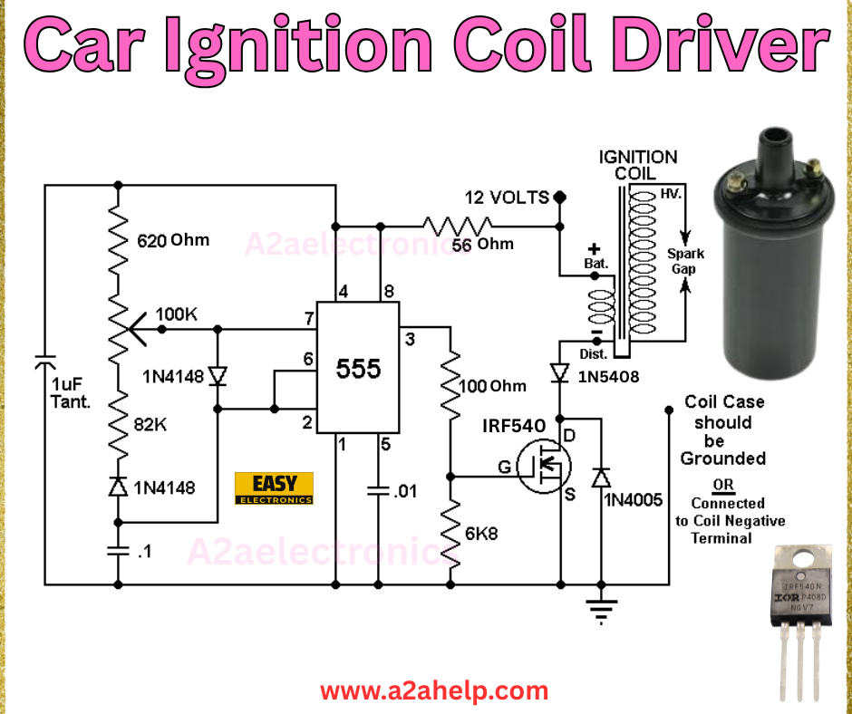
The schematic above outlines a car ignition coil driver circuit using a 555 timer in astable mode to generate pulses, driving an IRF540 MOSFET to switch the ignition coil. Here’s a breakdown of the components and their functions:
- 555 Timer IC (U1): Generates a square wave signal to control the MOSFET.
- IRF540 MOSFET (Q1): Acts as a switch to drive the ignition coil.
- Ignition Coil: Steps up the 12V input to a high-voltage output for the spark gap.
- R1 (620Ω): Limits current to the 555 timer.
- R2 (100kΩ) and R3 (82kΩ): Set the frequency of the 555 timer with C1.
- C1 (1µF Tantalum): Determines the pulse width alongside R2 and R3.
- R4 (56Ω): Provides base current for the MOSFET.
- R5 (100Ω): Limits current to the ignition coil.
- D1 (1N5408): Protects the circuit from voltage spikes.
- D2 (1N4005): Ensures proper diode action in the feedback loop.
- R6 (6.8kΩ): Stabilizes the MOSFET gate voltage.
- C2 (0.1µF): Filters noise in the circuit.

Step-by-Step Guide to Building the Car Ignition Coil Driver
Materials Needed
- 555 Timer IC
- IRF540 MOSFET
- Ignition coil (compatible with 12V)
- Resistors: 620Ω, 100kΩ, 82kΩ, 56Ω, 100Ω, 6.8kΩ
- Capacitors: 1µF Tantalum, 0.1µF
- Diodes: 1N5408, 1N4005
- 12V power supply (e.g., car battery)
- Breadboard or PCB
- Soldering iron, solder, and flux
- Multimeter and oscilloscope (for testing)
- Heat sink (for the MOSFET)
Assembly Instructions
- Set Up the 555 Timer: Place the 555 timer on your breadboard or PCB. Connect pin 4 (Reset) and pin 8 (Vcc) to 12V, and pin 1 (Ground) to the negative terminal.
- Configure the Oscillator: Connect R1 (620Ω) between pin 7 and 12V, R2 (100kΩ) between pin 7 and pin 6, and R3 (82kΩ) between pin 6 and pin 2. Add C1 (1µF) between pin 2 and ground.
- Connect the MOSFET: Attach the gate of the IRF540 (pin G) to pin 3 of the 555 timer via R4 (56Ω). Connect the source (pin S) to ground and the drain (pin D) to the ignition coil.
- Wire the Ignition Coil: Connect the positive terminal of the 12V supply to the ignition coil’s positive terminal. Link the coil’s negative terminal to the MOSFET drain. Ensure the coil case is grounded.
- Add Protection Components: Place D1 (1N5408) across the coil terminals to protect against back EMF. Connect R5 (100Ω) and D2 (1N4005) in series with the distributor (Dist.) point.
- Finalize the Circuit: Add R6 (6.8kΩ) from the MOSFET gate to ground and C2 (0.1µF) across the power supply for noise reduction.
- Test the Circuit: Apply 12V and use a multimeter to check the output. Observe the spark gap with an oscilloscope to verify high-voltage pulses.
Safety Tips
- Work with high voltages carefully to avoid electric shock.
- Use a heat sink on the MOSFET to prevent overheating.
- Disconnect the power supply when making adjustments.
Applications of a Car Ignition Coil Driver
This circuit is ideal for:
- Educational Projects: Learn about high-voltage generation and switching.
- Custom Engines: Test ignition systems in experimental vehicles.
- Science Experiments: Create sparks for demonstrations or plasma projects.
Troubleshooting Common Issues
- No Spark: Check the 555 timer connections and ensure the MOSFET is switching.
- Weak Spark: Verify the ignition coil and adjust the pulse frequency.
- Overheating: Add a larger heat sink or reduce the duty cycle.
Why Use a 555 Timer and IRF540?
The 555 timer offers a simple way to generate adjustable pulses, while the IRF540 MOSFET provides robust switching for high-current loads. Together, they make this circuit reliable and easy to build, even for beginners.
Conclusion
Building a car ignition coil driver with a 555 timer and IRF540 MOSFET is a rewarding project that combines automotive and electronics skills. Follow this guide to create your high-voltage spark generator. For more DIY electronics projects, visit www.a2ahelp.com. Got questions? Drop a comment below!
