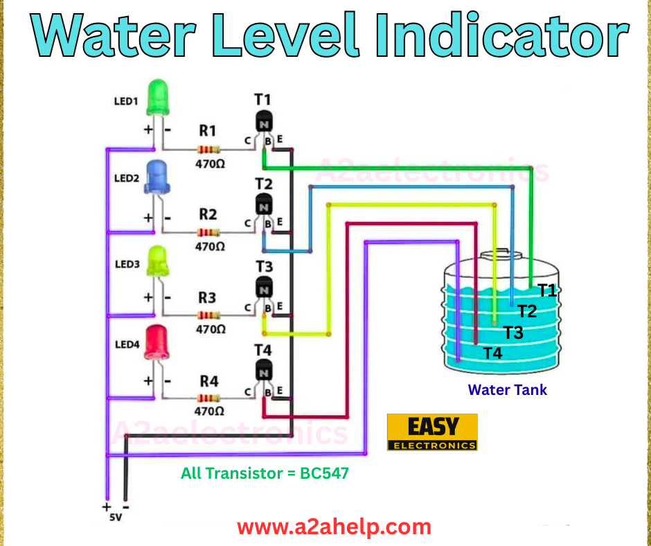
Are you looking for an efficient way to monitor water levels in your tank? A water level indicator circuit is a simple yet effective solution that can save you time and prevent overflow or dry run scenarios. In this comprehensive guide, we’ll walk you through the process of building a water level indicator using basic electronic components. Whether you’re a hobbyist or an experienced electronics engineer, this DIY project is perfect for enhancing your skills. Let’s dive in!
What is a Water Level Indicator?
A water level indicator is an electronic device that detects and displays the water level in a tank using LEDs. This circuit uses sensors placed at different levels to indicate when the water reaches specific heights. It’s an affordable and practical tool for households, industries, and agricultural settings.
Components Required
To build this water level indicator circuit, you’ll need the following components:
- BC547 Transistors (4 pieces)
- LEDs (4 pieces – green, blue, yellow, red)
- 470Ω Resistors (4 pieces)
- Wires
- 5V Power Supply
- Water Tank
- Probes (metal rods or wires for sensing)

Understanding the Circuit Diagram
The circuit diagram provided shows a straightforward design. Here’s a breakdown:
- Transistors (T1, T2, T3, T4): These BC547 NPN transistors act as switches, turning the LEDs on or off based on the water level.
- LEDs (LED1, LED2, LED3, LED4): Each LED represents a different water level – green for low, blue for quarter, yellow for half, and red for full.
- Resistors (R1, R2, R3, R4): These 470Ω resistors limit the current to the LEDs, protecting them from damage.
- Probes (T1, T2, T3, T4): Placed at different heights in the tank, these act as sensors. When water connects the probes to the common ground, the circuit completes.
The power supply is a 5V source, and the entire setup uses a common ground connected to the tank.
How the Water Level Indicator Works
The water level indicator operates on a simple principle of electrical conductivity. Water acts as a conductor between the probes and the ground. Here’s how it functions:
- When the water level is low, only the T1 probe is submerged, activating LED1 (green).
- As the water rises to the T2 probe, LED2 (blue) lights up, indicating a quarter level.
- At the T3 probe, LED3 (yellow) turns on, showing the half level.
- When the water reaches the T4 probe, LED4 (red) illuminates, signaling a full tank.
The transistors amplify the small current from the water to light up the LEDs, making the system reliable and easy to read.
Step-by-Step Guide to Build the Circuit
Step 1: Gather Materials
Ensure you have all the components listed above. You can purchase them from any electronics store or online marketplace.
Step 2: Set Up the Circuit
- Connect the emitter (E) of each BC547 transistor to the ground.
- Attach the collector (C) of each transistor to the positive terminal of the respective LED.
- Connect the other terminal of each LED to a 470Ω resistor, then to the 5V supply.
- Link the base (B) of each transistor to its corresponding probe (T1, T2, T3, T4).
- Place the probes at different heights inside the water tank, ensuring they don’t touch each other.
Step 3: Test the Circuit
Power the circuit with a 5V supply. Gradually fill the tank with water and observe the LEDs lighting up at each level. Adjust the probe positions if needed.
Step 4: Secure the Setup
Once tested, secure the probes and wiring to prevent movement. Ensure the tank is clean to avoid false readings due to debris.
Advantages of a Water Level Indicator
- Cost-Effective: Uses inexpensive components.
- Easy to Install: Simple design suitable for beginners.
- Real-Time Monitoring: Provides instant feedback on water levels.
- Prevents Overflows: Helps avoid water wastage.
Troubleshooting Tips
- LEDs Not Lighting Up: Check the power supply and connections. Ensure the probes are correctly placed.
- False Readings: Clean the tank and probes to remove any conductive residue.
- Weak LED Glow: Replace the resistors or increase the power supply voltage slightly (within safe limits).
Applications
This water level indicator is versatile and can be used in:
- Household water tanks
- Industrial storage units
- Agricultural irrigation systems
Conclusion
Building a water level indicator circuit is a rewarding DIY project that combines electronics knowledge with practical application. By following this guide, you can create a reliable system to monitor water levels efficiently. Whether you’re looking to save water or enhance your electronics skills, this project is a great starting point. Try it out today and share your experience with us!
