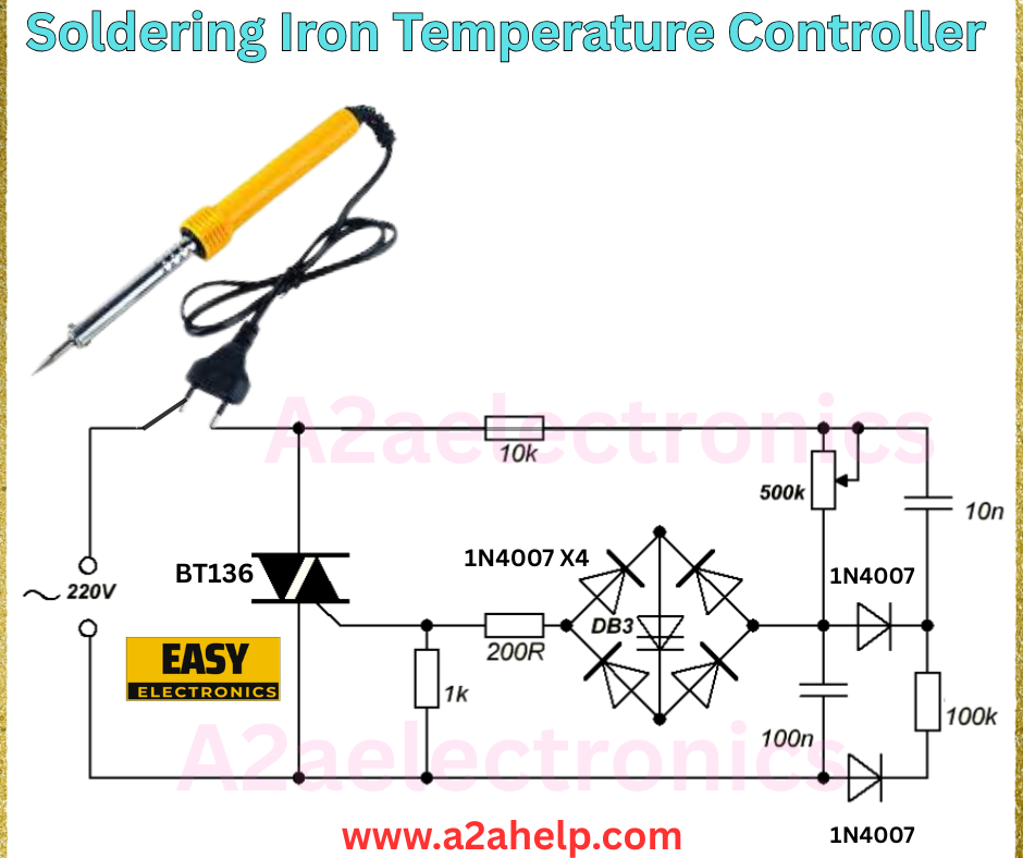
For hobbyists, DIY enthusiasts, and professional electronics engineers, maintaining the right temperature on a soldering iron is crucial for successful soldering projects. A soldering iron temperature controller allows you to adjust and stabilize the heat, preventing damage to sensitive components. In this article, we’ll explore a simple yet effective soldering iron temperature controller circuit, inspired by the schematic from www.a2ahelp.com, and guide you through its components, working principle, and benefits.
What is a Soldering Iron Temperature Controller?
A soldering iron temperature controller is an electronic circuit that regulates the temperature of a soldering iron by controlling the power supplied to its heating element. This ensures consistent heat levels, which is essential for soldering delicate circuits or working with various solder types. The circuit featured here uses a variable resistor to fine-tune the temperature, making it a practical DIY project for anyone interested in electronics.
Key Components of the Circuit
Let’s break down the essential parts of this temperature controller:
- BT136 TRIAC: A bidirectional switch that controls the AC power to the soldering iron based on the gate signal.
- 1N4007 Diodes (x4): Form a bridge rectifier to convert AC to DC for the control circuit.
- DB3 Diac: Triggers the TRIAC by providing a gate pulse when the voltage across it reaches a threshold.
- 200Ω Resistor: Limits the current to the Diac, ensuring stable operation.
- 1kΩ Resistor: Provides additional current limiting in the control loop.
- 100nF Capacitor: Smooths the voltage and works with the variable resistor to set the firing angle of the TRIAC.
- 500kΩ Potentiometer: Allows manual adjustment of the temperature by varying the charging time of the capacitor.
- 10nF Capacitor: Further stabilizes the circuit by filtering high-frequency noise.
- 100kΩ Resistor: Acts as a bleed resistor to discharge the capacitor when the circuit is off.
- 1N4007 Diode: Protects the circuit from reverse voltage spikes.
- 220V AC Supply: Powers the soldering iron and the control circuit.
- Soldering Iron: The device being controlled, connected to the output.

How the Circuit Works
This temperature controller operates using phase control to regulate the soldering iron’s heat:
- Power Input: The 220V AC supply powers the circuit and the soldering iron.
- Rectification: The 1N4007 diodes form a bridge rectifier, converting AC to a pulsating DC signal.
- Phase Control: The 500kΩ potentiometer and 100nF capacitor determine the charging time, which sets the firing angle of the TRIAC via the DB3 Diac. Adjusting the potentiometer changes the point in the AC cycle when the TRIAC conducts.
- Temperature Regulation: By controlling the portion of the AC cycle delivered to the soldering iron, the circuit adjusts the average power, thus regulating the temperature. Turning the potentiometer increases or decreases the heat.
- Protection: The additional 1N4007 diode and resistors safeguard the components from voltage spikes and ensure safe operation.
Benefits of a Temperature Controller
- Precision Soldering: Maintains optimal heat levels for different solder types and components.
- Component Safety: Prevents overheating, which can damage sensitive electronics.
- Energy Efficiency: Reduces power consumption by controlling the duty cycle.
- Cost-Effective: Uses affordable, widely available parts, perfect for a DIY build.
- Ease of Use: The adjustable potentiometer makes it user-friendly for beginners and experts alike.
Why This Circuit is a Game-Changer
Unlike basic soldering irons with fixed temperatures, this controller offers flexibility and control. The use of a TRIAC and Diac combination provides a reliable way to modulate power, while the simple design from A2A Electronics makes it accessible for home assembly. This circuit is ideal for anyone looking to upgrade their soldering setup without investing in expensive commercial tools.
How to Build Your Own
To create this soldering iron temperature controller, gather the listed components and follow the schematic carefully. Ensure proper insulation and use a heat-resistant enclosure for safety. Test the circuit with a multimeter before connecting the soldering iron. For a detailed guide, check out www.a2ahelp.com.
Conclusion
A soldering iron temperature controller is an invaluable tool for anyone working with electronics. This DIY circuit offers a practical solution to achieve precise temperature control, protecting your projects and enhancing your soldering skills. Build your own today and experience the difference it makes in your workbench!
