Are you tired of pesky mosquitoes and insects invading your home? Building a DIY Mosquito/Insect Killer circuit is a practical and cost-effective solution to keep your space bug-free. This project, inspired by the design from A2aelectronics, uses a high-voltage grid and UV lamp to attract and eliminate insects. In this detailed guide, we’ll break down the circuit diagram, components, and step-by-step instructions to help you create your own insect killer. Let’s dive in!
What is a Mosquito/Insect Killer Circuit?
A Mosquito/Insect Killer circuit is an electronic device that uses ultraviolet (UV) light to attract insects and a high-voltage grid to zap them. This particular design operates on a 230V AC supply and is simple enough for electronics hobbyists to assemble. The circuit, showcased by A2aelectronics, is both efficient and safe when handled with care.
Key Components of the Circuit
- Capacitors (C1-C6): 0.47/400V for voltage regulation
- Resistor (R1): 15kΩ, 10W for current limiting
- Resistor (R6): 560kΩ for high-voltage control
- Diodes (D1-D7): 1N4007 for rectification
- Capacitor (C7): 4.7µF/400V for filtering
- UV Lamp: 11W for attracting insects
- High-Voltage Grid: Generates the electric field to kill insects
- Power Supply: 230V AC
Step-by-Step Guide to Building the Mosquito/Insect Killer

1. Gather Your Materials
Collect all the components listed above. Ensure you have a soldering iron, breadboard, and insulated tools, as this circuit involves high voltage. Purchase parts from a trusted electronics supplier or recycle from old devices.
2. Study the Circuit Diagram
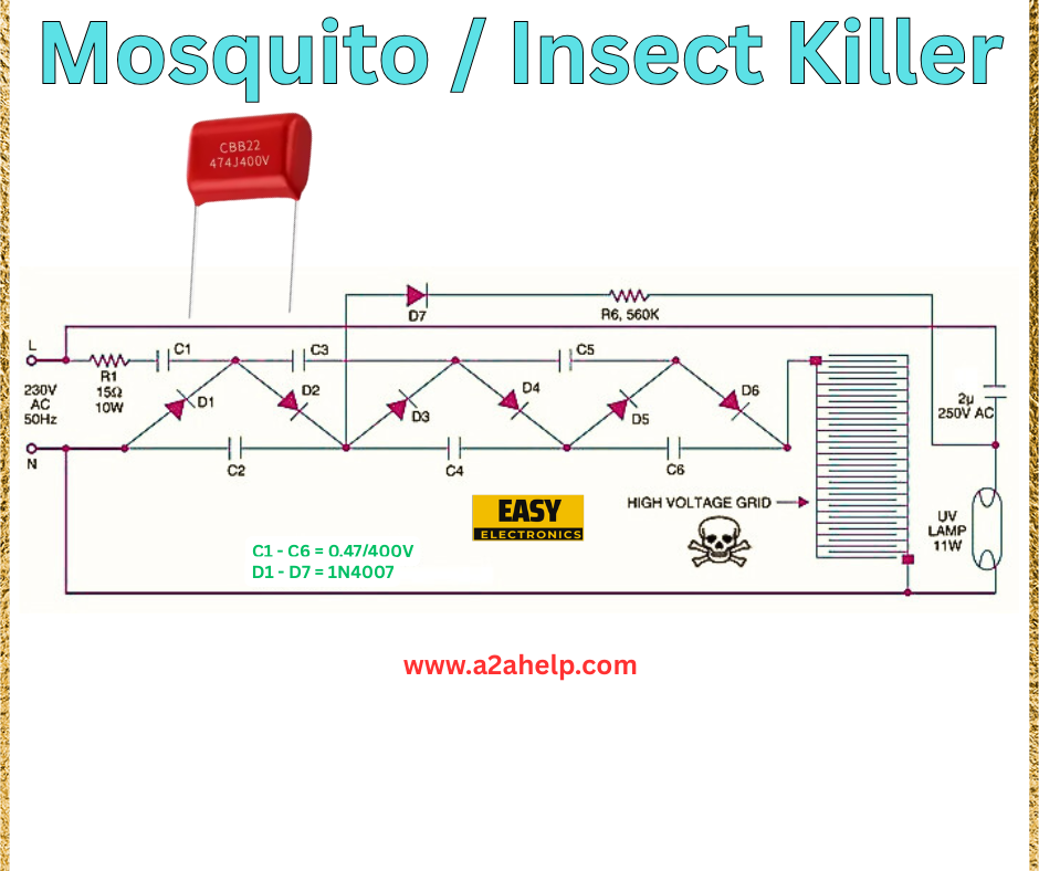
The schematic from A2aelectronics shows a straightforward design. The 230V AC supply enters through the live (L) and neutral (N) lines. R1 and C1-C6 form a voltage-dropping network, while D1-D7 rectify the AC to DC. The 560kΩ resistor (R6) and high-voltage grid create the electric field, and the 11W UV lamp attracts insects.
3. Assemble the Circuit
- Connect the 230V AC supply to the input terminals.
- Wire the 0.47/400V capacitors (C1-C6) in series with R1 (15kΩ, 10W) to step down the voltage.
- Use the 1N4007 diodes (D1-D7) to build a bridge rectifier.
- Attach the 4.7µF/400V capacitor (C7) for smoothing the DC output.
- Link the 560kΩ resistor (R6) to the high-voltage grid.
- Connect the 11W UV lamp in parallel with the grid.
4. Test and Install
Power on the circuit and ensure the UV lamp lights up. Check for a high-voltage discharge across the grid (use a multimeter with caution). Mount the device in an open area, away from children and pets, for safe operation.
Benefits of a DIY Mosquito/Insect Killer
- Eco-Friendly: Reduces reliance on chemical insecticides.
- Cost-Effective: Uses affordable components.
- Customizable: Adjust the design to suit your needs.
Safety Precautions
- High Voltage: Handle with care to avoid electric shock.
- Insulation: Use insulated wires and enclosures.
- Placement: Install in a dry, ventilated area away from water.
Troubleshooting Tips
- No Light: Verify the UV lamp connection and 230V supply.
- No Voltage: Check the diodes and capacitors for damage.
- Weak Performance: Ensure the high-voltage grid is properly wired.
Why Build Your Own Insect Killer?
This DIY Mosquito/Insect Killer project is perfect for electronics enthusiasts and homeowners seeking a sustainable pest control solution. It’s a great way to learn about high-voltage circuits and AC-to-DC conversion while solving a common problem. Plus, it’s a fun challenge with rewarding results!
Conclusion
Creating a Mosquito/Insect Killer circuit is a fantastic DIY project that combines practicality with electronics know-how. With the detailed schematic from A2aelectronics and this guide, you can build an effective insect trap for your home. Get started today and enjoy a bug-free environment! For more electronics projects, visit www.a2ahelp.com.
