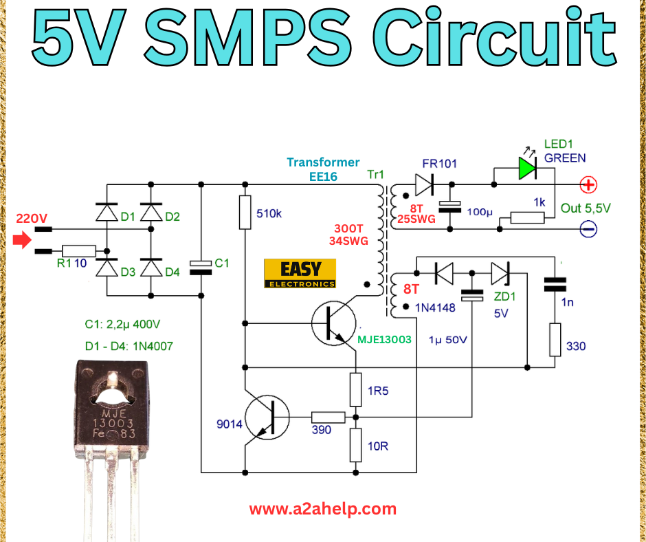
Are you looking for a reliable and efficient way to power your small electronic devices? A 5V Switch Mode Power Supply (SMPS) is an excellent choice for delivering stable voltage with high efficiency. In this detailed guide, we’ll walk you through building a 5V SMPS circuit using accessible components, perfect for hobbyists and professionals alike. This article includes a circuit analysis, component list, and assembly instructions to help you create your own power supply.
What is a 5V SMPS Circuit?
A Switch Mode Power Supply (SMPS) converts AC mains voltage into a stable DC output by switching the input at high frequencies. This 5V SMPS circuit is designed to provide a consistent 5.5V output, ideal for charging USB devices, powering microcontrollers, or running small LED systems. Its compact design and efficiency make it a popular choice for DIY electronics projects.
Components Required
Gather the following components to build your 5V SMPS:
- Transistor MJE13003: High-voltage switching transistor.
- Diodes: 1N4007 (x4, D1-D4), 1N4148 (Zener diode Z1), FR101.
- Transformer EE16: Custom-wound with 300T (25SWG) primary and 8T (25SWG) secondary.
- Capacitors: 2.2µF (400V, C1), 1µF (50V).
- Resistors: 510Ω, 10Ω, 330Ω, 1KΩ.
- LED: Green LED (LED1) for power indication.
- Miscellaneous: PCB, heat sink, and connecting wires.
Understanding the Circuit Diagram

- Input Stage: The 220V AC input is rectified by a bridge made of four 1N4007 diodes (D1-D4), producing a pulsating DC voltage.
- Switching Stage: The MJE13003 transistor switches the rectified voltage at high frequency, driven by a 510Ω resistor (R1) and a 2.2µF capacitor (C1).
- Transformer: The EE16 transformer steps down the voltage, with a 300-turn primary and 8-turn secondary winding using 25SWG wire.
- Output Stage: The secondary voltage is rectified by the FR101 diode and regulated to 5V using a 1N4148 Zener diode (Z1). A 1µF capacitor smooths the output, and a 1KΩ resistor with a green LED indicates power status.
Step-by-Step Assembly Guide
- Prepare the PCB: Etch or design a PCB based on the circuit layout. Ensure proper insulation for high-voltage sections.
- Mount the MJE13003: Solder the transistor onto the PCB and attach a heat sink to manage heat dissipation.
- Install Diodes: Place the 1N4007 diodes for the bridge rectifier and the FR101 for secondary rectification. Add the 1N4148 Zener diode.
- Wind the Transformer: Carefully wind the EE16 transformer with 300 turns (primary) and 8 turns (secondary) using 25SWG wire. Insulate the windings properly.
- Add Capacitors and Resistors: Solder the 2.2µF (C1) and 1µF capacitors, along with the 510Ω, 10Ω, 330Ω, and 1KΩ resistors.
- Connect the LED: Wire the green LED with a 1KΩ resistor for power indication.
- Final Connections: Link the input (220V AC) and output (5.5V) terminals. Double-check all connections.
- Testing: Power the circuit with a variac or dimmer. Use a multimeter to confirm a stable 5.5V output and ensure the LED lights up.
Safety Tips
- Handle 220V AC with care. Use insulated tools and wear protective gear.
- Ensure proper grounding to prevent electrical hazards.
- Test the circuit at a low voltage initially to identify issues.
Benefits of This 5V SMPS
- High Efficiency: Reduces power loss compared to linear supplies.
- Compact Size: Ideal for small-scale projects.
- Cost-Effective: Uses widely available components.
Troubleshooting Common Issues
- No Output: Check the transformer windings and diode orientation.
- Overheating: Ensure the MJE13003 has adequate cooling.
- Unstable Voltage: Verify capacitor values and Zener diode functionality.
Conclusion
Building a 5V SMPS circuit is a rewarding project for anyone interested in electronics. With this guide, you can create a reliable power supply for your devices using simple components and the provided circuit diagram. Follow the steps carefully, and enjoy the benefits of your homemade SMPS. For more electronics tutorials, visit www.a2ahelp.com.
