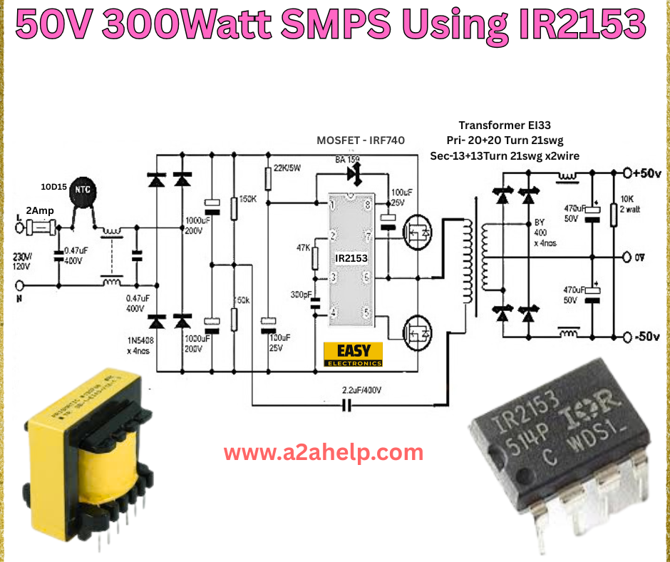
Are you looking to design a high-efficiency power supply for your electronic projects? A Switch Mode Power Supply (SMPS) is an excellent choice, offering compact size, high efficiency, and reliable performance. In this comprehensive guide, we’ll walk you through building a 50V 300W SMPS using the IR2153 IC, a popular choice among electronics enthusiasts and professionals. This article provides a detailed breakdown of the circuit diagram, components, and assembly process, ensuring you can create a robust power supply with ease.
What is an SMPS and Why Use the IR2153?
A Switch Mode Power Supply (SMPS) converts electrical power efficiently by switching the input voltage on and off at a high frequency. Unlike traditional linear power supplies, SMPS designs reduce energy waste and heat, making them ideal for modern applications. The IR2153 is a self-oscillating half-bridge driver IC widely used in SMPS designs due to its simplicity and integrated features, such as overcurrent protection and a built-in oscillator.
This 50V 300W SMPS project is perfect for powering amplifiers, LED lighting systems, or other high-power electronics, delivering a stable 50V output with a capacity of 300 watts.
Components Required
Before diving into the construction, gather the following components:
- IR2153 IC: The heart of the SMPS circuit.
- MOSFET IRF740: Used in the half-bridge configuration.
- Transformer E33: Custom-wound with 20-20 turns (primary) and 13-13 turns (secondary) using 21 SWG wire.
- Diodes (1N5408): 4 units for rectification.
- Capacitors: 0.47µF (400V), 1000µF (200V), 470µF (50V).
- Resistors: 15KΩ, 22KΩ, 10KΩ (2W), 47KΩ.
- NTC Thermistor (10D15): For inrush current limiting.
- Inductor: For filtering the output.
- Fuse: 2A for safety.
- Miscellaneous: PCB, heat sink, and connecting wires.
Understanding the Circuit Diagram

- Input Stage: The 220V AC input passes through a 2A fuse and an NTC thermistor to limit inrush current. It’s then filtered by a 0.47µF capacitor and rectified using a bridge configuration with 1N5408 diodes.
- Half-Bridge Section: The IR2153 IC drives two IRF740 MOSFETs in a half-bridge topology, oscillating at a high frequency to step down the voltage via the transformer.
- Transformer: The E33 transformer steps down the voltage, with a primary winding of 20-20 turns and a secondary winding of 13-13 turns using 21 SWG wire.
- Output Stage: The secondary voltage is rectified and filtered using 470µF capacitors and an inductor, delivering a stable 50V DC output.
Step-by-Step Assembly Guide
- Prepare the PCB: Etch or design a PCB based on the circuit diagram. Ensure proper spacing for high-voltage components.
- Mount the IR2153 IC: Place the IC in the center of the PCB and solder it securely. Add a heat sink if required.
- Install MOSFETs: Attach the IRF740 MOSFETs to the half-bridge section, ensuring they are mounted on heat sinks for thermal management.
- Wind the Transformer: Carefully wind the E33 transformer as per the specified turns (20-20 primary, 13-13 secondary). Use 21 SWG wire and insulate properly.
- Connect Diodes and Capacitors: Solder the 1N5408 diodes for rectification and the capacitors for smoothing the output voltage.
- Add Resistors and Inductor: Place the resistors and inductor in their designated positions to complete the filtering circuit.
- Final Connections: Wire the fuse, NTC thermistor, and output terminals. Double-check all connections for accuracy.
- Testing: Power on the circuit with a variac or dimmer to ensure the output stabilizes at 50V. Use a multimeter to verify the voltage and current.
Safety Tips
- Always work with AC mains power cautiously. Use insulated tools and wear protective gear.
- Ensure proper grounding to avoid electrical shocks.
- Test the circuit at a low voltage initially to identify potential issues.
Benefits of This SMPS Design
- High Efficiency: The switching design minimizes power loss.
- Compact Size: Ideal for space-constrained projects.
- Cost-Effective: Uses readily available components like the IR2153 and IRF740.
Troubleshooting Common Issues
- No Output Voltage: Check the transformer windings and MOSFET connections.
- Overheating: Ensure proper heat sinking and verify the load is within 300W.
- Instability: Adjust the capacitor values or check for loose connections.
Conclusion
Building a 50V 300W SMPS using IR2153 is a rewarding project for electronics hobbyists and professionals alike. With the right components and careful assembly, you can create a reliable power supply for various applications. Follow this guide, refer to the circuit diagram, and enjoy the process of bringing your SMPS to life. For more electronics projects and tutorials, visit www.a2ahelp.com.
