Looking to harness the power of the sun for your lighting needs? A mini solar light circuit is an eco-friendly and cost-effective solution for illuminating small spaces. In this detailed guide, we’ll analyze the provided circuit diagram and walk you through building your own mini solar light. Perfect for electronics enthusiasts and DIYers, this tutorial covers the components, assembly, and working principle to help you create a sustainable lighting solution.
Understanding the Mini Solar Light Circuit
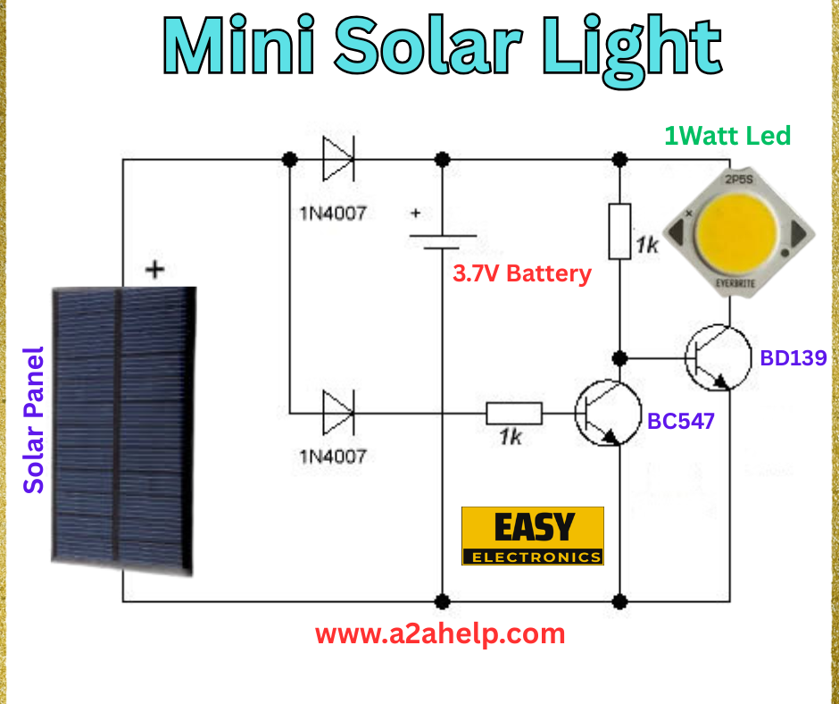
The circuit diagram above depicts a simple mini solar light that uses a solar panel to charge a 3.7V battery during the day and powers a 1W LED at night. This design incorporates diodes and transistors to manage power flow and ensure efficient operation. Let’s break down the components and their roles in this circuit.

Components Required
- Solar Panel: Converts sunlight into electrical energy (typically 5-6V output).
- 1N4007 Diodes: Prevent reverse current flow from the battery to the solar panel.
- 3.7V Battery: Stores the energy harvested by the solar panel.
- 1K Resistors: Limit current to the transistor and LED.
- BC547 Transistor: Acts as a switch to control the LED.
- BD139 Transistor: Amplifies the current to drive the LED.
- 1W LED: Provides the illumination (e.g., EverBrite brand).
Circuit Diagram Analysis
- Charging Stage: The solar panel charges the 3.7V battery through the 1N4007 diodes, which prevent reverse current. The diodes ensure the battery only charges when the panel produces sufficient voltage.
- Switching Stage: The BC547 transistor, triggered by the battery voltage, controls the circuit. When the solar panel voltage drops (e.g., at night), the transistor activates the BD139.
- Lighting Stage: The BD139 transistor amplifies the current, powering the 1W LED through a 1K resistor to limit the current and protect the LED.
Step-by-Step Assembly Guide
- Connect the Solar Panel: Attach the positive terminal of the solar panel to the anode of the first 1N4007 diode. Link the cathode to the second diode’s anode, and connect the cathode to the battery’s positive terminal.
- Install the Battery: Solder the 3.7V battery, ensuring the positive terminal connects to the diode chain and the negative terminal to the circuit ground.
- Add the Transistors: Mount the BC547 transistor, connecting its base to the battery’s positive via a 1K resistor and its collector to the BD139 base. Attach the BD139, linking its collector to the LED and emitter to ground.
- Connect the LED: Solder the 1W LED, with its positive leg to the BD139 collector and negative leg to a 1K resistor, then to ground.
- Test the Circuit: Place the solar panel in sunlight to charge the battery. At dusk, the LED should light up automatically. Verify connections with a multimeter.
Working Principle
During the day, the solar panel generates voltage that charges the 3.7V battery through the 1N4007 diodes. At night, when the panel voltage drops, the BC547 transistor detects this change and turns on the BD139 transistor. The BD139 then supplies current to the 1W LED, illuminating your space. The 1K resistors ensure safe current levels, making this a reliable solar light system.
Safety Tips
- Use a heat sink with the BD139 transistor to prevent overheating.
- Ensure proper polarity when connecting the battery and LED.
- Test the circuit in a shaded area initially to avoid damage from overvoltage.
Applications
This mini solar light is ideal for garden lighting, pathways, or emergency lighting in remote areas.
Conclusion
Building a mini solar light circuit is a great way to explore renewable energy projects. By following this guide and using the provided diagram, you can create an efficient solar-powered light for your home. For more electronics tutorials and projects, visit www.a2ahelp.com. Have questions? Leave a comment below!

