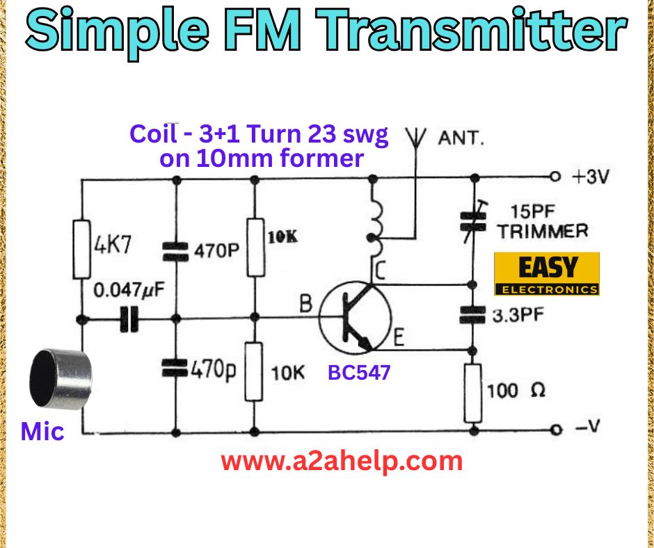
Are you an electronics enthusiast eager to create your own FM transmitter for broadcasting audio signals? Building a simple FM transmitter is a fun and educational project that lets you explore radio frequency (RF) circuits. In this comprehensive guide, we’ll walk you through constructing a basic FM transmitter using a straightforward circuit diagram. Perfect for beginners and hobbyists, this tutorial will help you get your voice or music on the air. Let’s dive in!
Understanding the Simple FM Transmitter Circuit
An FM transmitter converts audio signals into radio waves and broadcasts them over a specific frequency. This circuit uses a BC547 transistor as the core oscillator, a custom coil for tuning, and minimal components to keep it simple yet effective. The design is ideal for short-range transmission, such as within a room or small area.
Components Required
- Microphone (Mic): Captures the audio input.
- 4.7kΩ Resistor: Biases the transistor base.
- 10kΩ Resistors (x2): Sets the operating point and feedback.
- 0.047µF Capacitor: Couples the audio signal.
- 470pF Capacitors (x2): Filters and tunes the circuit.
- 3.3pF Capacitor: Part of the oscillator tank circuit.
- 15pF Trimmer Capacitor: Adjusts the transmission frequency.
- 100Ω Resistor: Limits current to the antenna.
- BC547 Transistor: Amplifies and oscillates the signal.
- Coil: 3+1 turns of 23 SWG wire on a 10mm former.
- Antenna (ANT): Simple wire for broadcasting.
- 3V Power Supply: Powers the circuit.
- Connecting Wires and Breadboard: For assembly.
Step-by-Step Guide to Building the FM Transmitter

Step 1: Gather Your Tools and Components
Collect all the listed components and tools, including a soldering iron, multimeter, and insulated wires. A steady hand and a quiet workspace will help with assembly and testing.
Step 2: Set Up the Audio Input
Connect the microphone to the circuit. Attach a 4.7kΩ resistor and a 0.047µF capacitor in series from the mic to the base (B) of the BC547 transistor. This couples the audio signal into the oscillator.
Step 3: Configure the Transistor Biasing
Connect a 10kΩ resistor from the base (B) to the +3V supply and another 10kΩ resistor from the emitter (E) to ground. Add a 470pF capacitor between the emitter and ground to stabilize the circuit.
Step 4: Build the Oscillator Tank Circuit
Create the coil by winding 3+1 turns of 23 SWG wire on a 10mm former. Connect one end of the coil to the collector (C) of the BC547 and the other end to the +3V supply. Add a 15pF trimmer capacitor and a 3.3pF capacitor in parallel with the coil to form the tank circuit, which determines the transmission frequency.
Step 5: Add the Output Stage
Connect a 470pF capacitor from the collector to a 100Ω resistor, then to the antenna. The antenna can be a simple wire (about 20-30 cm long) for short-range transmission.
Step 6: Power the Circuit
Apply a 3V power supply to the circuit. Connect the positive terminal to the junction of the coil and trimmer, and the negative terminal to ground.
Step 7: Test and Tune the Transmitter
Turn on the power supply and speak into the microphone. Use an FM radio tuned to the 88-108 MHz band to locate the transmitted signal. Adjust the 15pF trimmer capacitor to fine-tune the frequency. Ensure the signal is clear and free of interference.
Safety Tips for Building Your FM Transmitter
- Use a low-power supply (3V) to comply with local regulations.
- Keep the antenna short to avoid interference.
- Avoid prolonged exposure to the antenna while transmitting.
- Test in an open area away from sensitive electronics.
Benefits of a DIY FM Transmitter
- Educational: Learn about RF circuits and oscillations.
- Cost-Effective: Build with affordable components.
- Customizable: Adjust for different frequencies or ranges.
Troubleshooting Common Issues
- No Transmission: Check power supply and coil connections.
- Weak Signal: Adjust the trimmer capacitor or extend the antenna.
- Interference: Ensure proper grounding and reduce nearby electronic noise.
Conclusion
Building a simple FM transmitter is a rewarding project for electronics enthusiasts. With this guide, you can create a functional transmitter using basic components and enjoy broadcasting your audio. For more electronics projects and tutorials, visit www.a2ahelp.com. Start your DIY adventure today and get on the airwaves!
