Introduction to Switch Mode Power Supplies (SMPS)
A Switch Mode Power Supply (SMPS) is an efficient way to convert and regulate voltage for electronic devices. Unlike linear power supplies, SMPS designs use high-frequency switching to minimize energy loss, making them compact and energy-efficient. This article explores a 7-9V SMPS circuit that uses a transformer with an EE16/19 core, delivering a stable DC output for low-power applications like LED drivers or small electronics.
Circuit Overview: How Does a 7-9V SMPS Work?
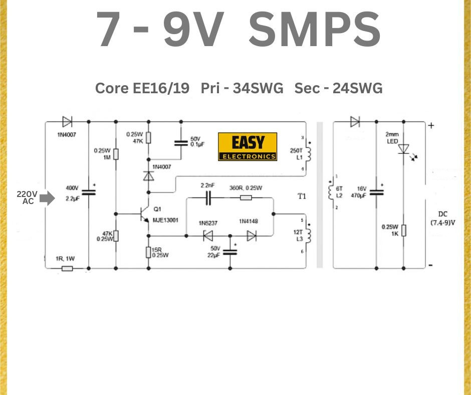
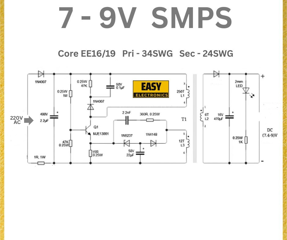
This SMPS circuit converts a 220V AC input into a regulated 7-9V DC output. It employs a flyback topology, utilizing a transformer (T1) with an EE16/19 core, an MJE13001 transistor for switching, and feedback components to regulate the output voltage. The design is split into primary and secondary sides, isolated by the transformer.
Key Components of the 7-9V SMPS Circuit
- Input Protection and Filtering:
- 1R, 1W Resistor: Acts as a fuse for overcurrent protection on the 220V AC input.
- IN4007 Diode: Rectifies the AC input to DC.
- 0.25W, 47kΩ Resistor and 2.2µF, 400V Capacitor: Form a filter to smooth the rectified DC and reduce noise.
- Switching Transistor (Q1, MJE13001):
- The MJE13001 is a high-voltage NPN transistor rated for 400V and 0.2A, suitable for switching in SMPS designs.
- It drives the primary winding of the transformer, enabling high-frequency switching.
- Transformer (T1, EE16/19 Core):
- Primary winding: 34 turns of 5WG wire.
- Secondary winding: 24 turns of 5WG wire.
- The EE16/19 core is a compact ferrite core, ideal for low-power SMPS applications.
- Feedback and Regulation:
- 1N5237 Zener Diode (8.2V) and 1N4148 Diode: Provide voltage feedback to regulate the output.
- 15R, 0.25W Resistor: Limits current in the feedback loop.
- 50V, 22µF Capacitor: Stabilizes the feedback circuit.
- Output Stage:
- 2mm LED: Indicates power-on status.
- 16V, 470µF Capacitor: Smooth the output voltage.
- 0.25W, 1kΩ Resistor: Limits current to the LED.

How the 7-9V SMPS Circuit Works
- AC to DC Conversion:
- The 220V AC input is rectified by the IN4007 diode into pulsating DC.
- The 2.2µF, 400V capacitor filters this voltage, providing a stable DC input to the primary side.
- High-Frequency Switching:
- The MJE13001 transistor switches the primary winding of the transformer at a high frequency (typically tens of kHz).
- This switching action induces a voltage in the secondary winding via magnetic coupling in the EE16/19 core.
- Voltage Regulation:
- The secondary winding produces a voltage proportional to the turns ratio (24:34), stepped down from the primary.
- The 1N5237 Zener diode (8.2V) and 1N4148 diode form a feedback loop, ensuring the output stays within 7-9V.
- The 470µF, 16V capacitor smooths the output, delivering a stable DC voltage.
- LED Indicator:
- The 3mm LED, in series with a 1kΩ resistor, lights up to indicate the circuit is operational.
Practical Tips for Building a 7-9V SMPS
- Transformer Winding:
- Ensure proper insulation between primary and secondary windings to maintain isolation and safety.
- The EE16/19 core should be gapped appropriately to prevent saturation during operation.
- Component Ratings:
- The 2.2µF capacitor must be rated for 400V to handle the rectified 220V AC (peak voltage ≈ 310V).
- The MJE13001 transistor should be mounted on a small heatsink if operating at high frequencies or loads.
- Safety Considerations:
- The primary side operates at high voltage (220V AC). Use proper insulation and a non-conductive enclosure.
- Add a varistor or MOV (Metal Oxide Varistor) across the AC input for surge protection.
- Efficiency and Heat:
- SMPS designs are efficient, but the MJE13001 may still generate heat during switching. Ensure adequate ventilation.
- Use a high-quality ferrite core to minimize core losses.
Applications of a 7-9V SMPS
- LED Drivers: Powers low-voltage LED strips or modules.
- Small Electronics: Supplies stable voltage for microcontrollers or sensors.
- Battery Charging: Provides a regulated voltage for charging 6V or 7.2V battery packs.
Conclusion
This 7-9V SMPS circuit is a compact and efficient solution for low-power applications. Using a flyback topology with an EE16/19 core transformer, it delivers a stable output while maintaining isolation between input and output. By following the design tips and ensuring safety, you can build a reliable power supply for your electronics projects.

