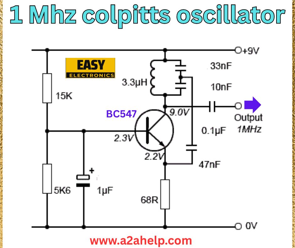
If you’re an electronics hobbyist or a professional looking to design a reliable 1 MHz Colpitts oscillator, you’re in the right place! In this guide, we’ll break down a simple yet effective 1 MHz Colpitts oscillator circuit, analyze its components, and explain how to build it. Whether you’re working on a radio frequency (RF) project or learning about oscillators, this article will provide you with all the insights you need to succeed.
What is a Colpitts Oscillator?
A Colpitts oscillator is a type of LC oscillator that generates sinusoidal signals using a combination of inductors (L) and capacitors (C). It’s widely used in RF applications, such as in radio transmitters, receivers, and signal generators, due to its stability and simplicity. The circuit in the image operates at 1 MHz, making it ideal for low-frequency RF projects.
Understanding the 1 MHz Colpitts Oscillator Circuit
Let’s dive into the circuit diagram and analyze its components:
- Power Supply: The circuit operates on a 9V DC supply, with the positive terminal connected to the top rail and the ground (0V) at the bottom.
- Transistor (BC547): The BC547, an NPN transistor, acts as the active component for amplification. It’s configured in a common-emitter setup to provide the necessary gain for oscillation.
- Inductor (3.3 µH): This inductor forms part of the LC tank circuit, which determines the oscillation frequency.
- Capacitors (33 nF, 10 nF, 47 nF, 0.1 µF, 1 µF): These capacitors serve multiple roles:
- The 33 nF and 10 nF capacitors form the capacitive voltage divider in the LC tank circuit, a hallmark of the Colpitts design.
- The 47 nF capacitor at the emitter stabilizes the transistor’s operation.
- The 0.1 µF capacitor at the output filters high-frequency noise.
- The 1 µF capacitor at the base decouples the DC bias from the input signal.
- Resistors (15 kΩ, 5.6 kΩ, 68 Ω): These resistors set the biasing for the transistor:
- The 15 kΩ and 5.6 kΩ resistors form a voltage divider to bias the base of the BC547.
- The 68 Ω resistor at the emitter provides negative feedback for stable operation.
- Output: The output is taken across the 0.1 µF capacitor, delivering a 1 MHz sinusoidal signal.
How Does the Circuit Work?
The Colpitts oscillator works by creating positive feedback through the LC tank circuit. The 3.3 µH inductor and the effective capacitance of the 33 nF and 10 nF capacitors (in series) resonate at 1 MHz. The BC547 transistor amplifies this resonant signal, and the feedback loop sustains the oscillation. The output voltage at the collector (2.3V) and emitter (2.2V) indicates the circuit is operating correctly, with the final 1 MHz signal available at the output terminal.

Step-by-Step Guide to Building the 1 MHz Colpitts Oscillator
- Gather Your Components:
- BC547 NPN transistor
- 3.3 µH inductor
- Capacitors: 33 nF, 10 nF, 47 nF, 0.1 µF, 1 µF
- Resistors: 15 kΩ, 5.6 kΩ, 68 Ω
- 9V power supply (e.g., a 9V battery)
- Breadboard or PCB for assembly
- Set Up the Transistor:
- Place the BC547 on your breadboard.
- Connect the collector to the 9V supply through the 3.3 µH inductor.
- Connect the emitter to ground through the 68 Ω resistor and 47 nF capacitor in parallel.
- Create the LC Tank Circuit:
- Connect the 33 nF capacitor between the collector and the base of the BC547.
- Connect the 10 nF capacitor from the base to ground.
- These capacitors, along with the 3.3 µH inductor, form the resonant tank circuit.
- Bias the Transistor:
- Connect the 15 kΩ resistor from the 9V supply to the base.
- Connect the 5.6 kΩ resistor from the base to ground.
- Add the 1 µF capacitor between the base and ground for decoupling.
- Extract the Output:
- Connect the 0.1 µF capacitor to the collector of the BC547.
- The other end of this capacitor is your 1 MHz output signal.
- Power Up and Test:
- Connect the 9V power supply.
- Use an oscilloscope to verify the 1 MHz sinusoidal output at the output terminal.
Tips for Optimizing Performance
- Component Quality: Use high-quality capacitors and inductors to minimize losses and ensure stable oscillation.
- Frequency Tuning: If the frequency deviates, adjust the inductor or capacitor values slightly. For example, a smaller inductor will increase the frequency.
- Shielding: If you’re using this in an RF project, shield the circuit to prevent interference.
- Power Supply: Ensure a stable 9V supply—consider adding a voltage regulator if needed.
Applications of a 1 MHz Colpitts Oscillator
This 1 MHz oscillator can be used in:
- RF Signal Generation: Ideal for testing RF circuits or as a local oscillator in radio receivers.
- Educational Projects: Perfect for learning about LC oscillators and transistor circuits.
- Tone Generation: Can be used in audio applications to generate a 1 MHz tone for testing.
Why Choose a Colpitts Oscillator?
Compared to other oscillators like Hartley or crystal oscillators, the Colpitts design is simpler and requires fewer components. It’s also less sensitive to parasitic effects, making it a great choice for beginners and professionals alike.
Conclusion
Building a 1 MHz Colpitts oscillator is a rewarding project that combines fundamental electronics principles with practical application. With just a handful of components, you can create a stable 1 MHz signal for your RF or educational projects. Follow the steps above, double-check your connections, and you’ll have a working oscillator in no time!
If you found this guide helpful, share it with your fellow electronics enthusiasts, and let us know your results in the comments below. Happy building!
